| Previous chapter | Next section | Next chapter | |
| ToC | Computers And Internet | MPEG-4 Inside – Visual | Software And Communication |
Many papers and books were published that explained the MPEG-4 standard using the figure below, originally contributed by Phil Chou, then with Xerox PARC. This page will be no different :-).
We will use the case of a publisher of technical courses who expected to do a better job by using MPEG-4 as opposed to what was possible in the mid 1990s using a DVD as distribution medium.
Such a publisher would hire a professional presenter to show his slides and would make videos of him. The recorded lessons would be copied on DVD and distributed. If anything changed, e.g. the publisher wanted to make the version of a successful course in another language, another presenter capable of speaking that particular language would be hired, the slides would be translated and a new version of the course would be published.
With MPEG-4, however, a publisher could reach a wider audience while cutting distribution costs.
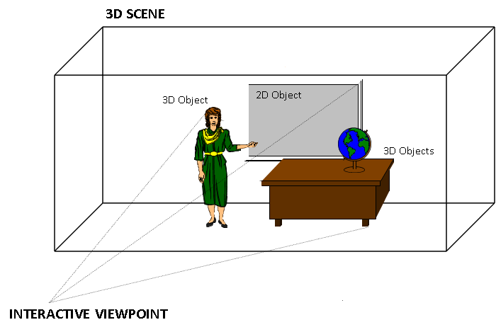
Figure 1 – A 3D scene suitable for MPEG-4
In the Figure, the standing lady is the presenter, making her lecture using a multimedia presentation next to a desk with a globe on it. In the example, the publisher makes video clips of the professional presenter while she is talking, but this time the video is made while she has a blue screen as background. The blue screen is useful because it is possible to extract just the shape of the presenter using “chroma key”, a well-known technique used in television to effect composition. The presenter’s voice is recorded in a way that it is easy to dub it and translate the audio-visual support material in case a multilingual edition of the course is needed. There is no need to change the video.
Having the teacher as a separate video sprite, a professional designer could create a virtual set made up of a synthetic room with some synthetic furniture and the frame of a blackboard that is used to display the audio-visual support material. In the figure above there are the following objects:
- presenter (video sprite)
- presenter (speech)
- multimedia presentation
- desk
- globe
- background
With these it was possible to create an MPEG-4 scene composed of audio-visual objects: static “objects” (e.g. the desk that stays unchanged for the duration of the lesson) and dynamic “objects” (e.g. the sprite and the accompanying voice, and the sequence of slides).

Figure 2 – An MPEG-4 scene
Of course, an authoring tool was needed so that the author could place the sprite of the presenter anywhere it was needed, e.g. near the blackboard and then store all the objects and the scene description in the MP4 File Format. This presentation could be ‘local’ to the system containing the presentation, or may be via a network or another stream delivery mechanism. The file format was also designed to be independent of a particular delivery protocol but enabled efficient support for delivery in general.
At the end user side, a subscriber to the course, after completing some forms of payment or authentication (outside of the MPEG-4 standard), could access the course. To do this, the first thing that was needed was the setting up of a session between the client and the server. This was done using DMIF, the MPEG-4 session protocol for the management of multimedia streaming. When the session with the remote side was set up, the streams needed for the particular lesson were selected and the DMIF client sent a request to stream them. The DMIF server returned the pointers to the connections where the streams coulf be found, and finally the connections were established. Then each audio-visual object was streamed using a virtual channel called Elementary Stream (ES) through the Elementary Stream Interface (ESI). The functionality provided by DMIF was expressed by the DAI as in the figure below, and translated into protocol messages. In general different networks used different protocol messages, but the DAI allowed the DMIF user to specify the Quality of Service (QoS) requirements for the desired streams.
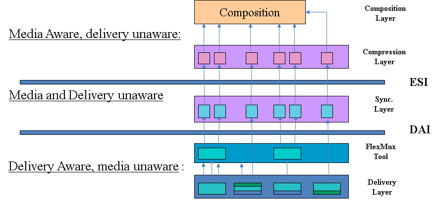
Figure 3 – The 3 layers in the MPEG-4 stack
The “TransMux” (Transport Multiplexing) layer offered transport services matching the requested QoS. However, only the interface to this layer was specified because the specific choice of the TransMux was left to the user. The specification of the TransMux itself was left to bodies responsible for the relevant transport, with the obvious exception of MPEG-2 TS, whose body in charge was MPEG itself. The second multiplexing layer was the M4Mux, which allowed grouping of ESs with a low multiplexing overhead. This was particularly useful when there were many ESs with similar QoS requirements, each possibly with a low bitrate. In this case it was possible to reduce the number of network connections, the transmission overhead and the end-to-end delay.
The special ES containing the Scene Description played a unique role. The Scene Description was a graph represented by a tree, like in the figure below that refers to the scene used in Figure 2.

Figure 4 – An MPEG-4 scene graph
With reference to the specific example, at the top of the graph we have the full scene with four branches: the background, the person, the audio-visual presentation and the furniture. The first branch is a “leaf” because there is no further subdivision, but the second and fourth are further subdivided. The object “person” is composed of two media objects: a visual object and an audio object (the lady’s video and voice). The object “furniture” is composed of two visual objects, the desk and the globe. The audio-visual presentation may be itself another scene. The ESs carry the information corresponding to the individual “leaves”, they are decompressed by the appropriate decoders and composed in a 3D space using information provided by the scene description.
The other important feature of the DAI was the provision of a uniform interface to access multimedia contents on different delivery technologies. This means that the part of the MPEG-4 player sitting on top of the DAI is independent of the actual type of delivery: interactive networks, broadcast and local storage. This can be seen from the figure below. In the case of a remote connection via the network there could be a real DMIF peer at the server, while in the local disk and broadcast access cases there was a simulated DMIF peer at the client.
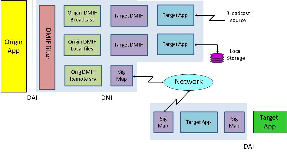
Figure 5 – DMIF independence from delivery mechanism
In the same way MPEG-1 and MPEG-2 describe the behaviour of an idealised decoding device along with the bitstream syntax and semantics, MPEG-4 defines a System Decoder Model (SDM). The purpose of SDM was to define precisely the operation of the terminal without unnecessary assumptions about implementation details that may depend on a specific environment. As an example, there could be devices receiving MPEG-4 streams over isochronous networks, while others could use non-isochronous means (e.g. the internet). The specification of a buffer and timing model was essential to design encoding devices that could be unaware of what the terminal device was or how it could receive the encoded stream. Each stream carrying media objects was characterised by a set of descriptors for configuration information, e.g. to determine the precision of encoded timing information. The descriptors could carry “hints” to the QoS required for transmission (e.g. maximum bit rate, bit error rate, priority, etc.).
ESs were subdivided in Access Units (AU). Each AU was time stamped for the purpose of ES synchronisation. The synchronisation layer managed the identification of such AUs and the time stamping. ESs coming from the demultiplexing function were stored in Decoding Buffers (DB) and the individual Media Object Decoders (MOD) read the data from there. The Elementary Stream Interface (ESI) was located between DBs and MODs, as depicted in Fig. 6.

Figure 6 – The MPEG-4 decoder model
Figure 7 represents the functions of an MPEG-4 decoder.
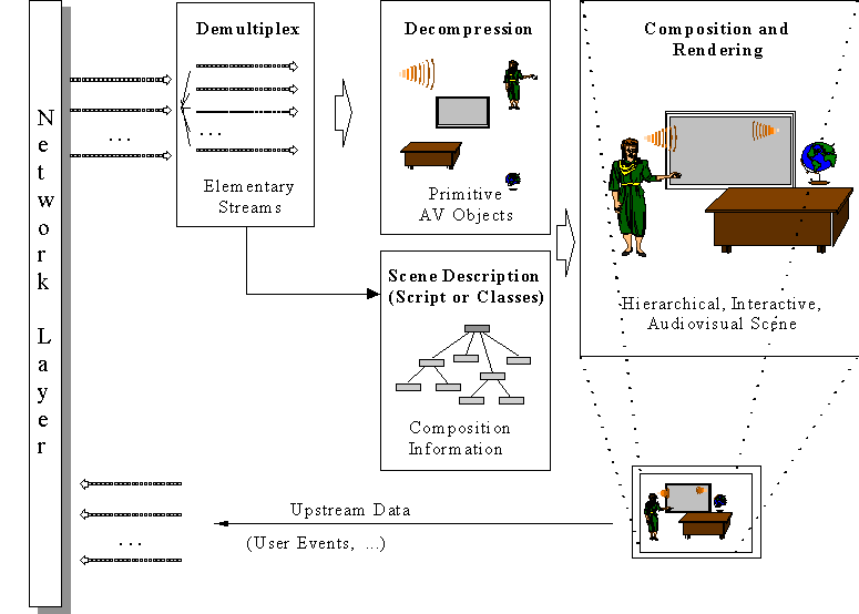
Figure 7 – Functions of an MPEG-4 decoder model
Depending on the viewpoint selected by the user, the 3D space generated by the MPEG-4 decoder could be projected onto a 2D plane and rendered: the visual part of the scene was displayed on the screen and the audio part was generated from the loudspeakers. The user could hear the lesson and view the presentation in the language of his choice by interacting with the content. This interaction could be separated into two major categories: client-side interaction and server-side interaction. Client-side interaction involved locally handled content manipulation, and could take several forms. In particular, the modification of an attribute of a scene description node, e.g. changing the position of an object, making it visible or invisible, changing the font size of a synthetic text node, etc., could be implemented by translating user events, such as mouse clicks or keyboard commands, to scene description updates. The MPEG-4 terminal could process the commands in exactly the same way as if they had been embedded in the content. Other interactions required sending commands to the information source using the upstream data channel.
What if the publisher had successfully entered the business of selling content on the web, and one day he discovers that his content can be found on the web for people to enjoy without getting it from the publisher? The publisher could use MPEG-4 technology to protect the Intellectual Property Rights (IPR) related to his course.
A first level of content management was achieved by adding the Intellectual Property Identification (IPI) data set to the coded media objects. This carried information about the content, type of content and (pointers to) rights holders, e.g. the publisher or other people from whom the right to use content had been acquired. The mechanism provided a registration number similar to the well established International Standard Recording Code (ISRC) used in CD Audio. This was a possible solution because another publisher could be quite happy to let users freely exchange information, provided the rights holder’s name was mentioned, but for other parts of the content, the information could have greater value so that higher-grade technology for management and protection was needed.
MPEG-4 specified the MPEG-4 IPMP interface allowing the design and use of domain-specific IPMP Systems (IPMP-S). This interface consisted of IPMP-Descriptors (IPMP-D) and IPMP-Elementary Streams (IPMP-ES) that provided a communication mechanism between IPMP-Ss and the MPEG-4 terminal. When MPEG-4 objects required management and protection, they had IPMP-Ds associated with them to indicate which IPMP-Ss were to be used and provided information about content management and protection. It is to be noted that, unlike MPEG-2 where a single IPMP system is used at a time, in MPEG-4 different streams could require different IPMP-Ss. Figure 8 describes these concepts.
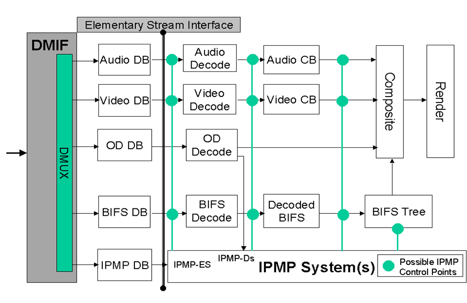
Figure 8 – The MPEG-4 IPMP model
MPEG-4 IPMP was a powerful mechanism. As an examples it allowed to “buy” the right to use certain content already in protected form from a third party.
Another useful feature to make content more interesting was to add programmatic content to the scene. The technology used was called MPEG-J, a programmatic system (as opposed to the purely declarative system). This specified APIs to enable Java code to manage the operation of the MPEG-4 player. By combining MPEG-4 media and executable code, one could achieve functionalities that would have been cumbersome to achieve just with the declarative part of the standard (see figure below).
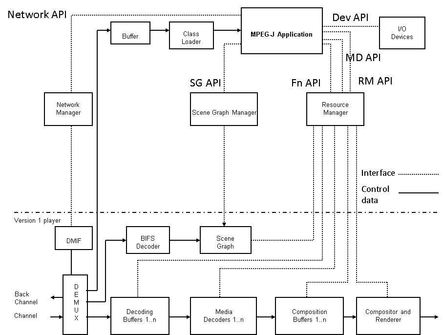
Figure 9 – MPEG-J model
The lower half of this drawing represents the parametric MPEG-4 Systems player also referred to as the Presentation Engine. The MPEG-J subsystem controlling the Presentation Engine, also referred to as the Application Engine, is depicted in the upper half of the figure. The Java application is delivered as a separate elementary stream to the MPEG-J run time environment of the MPEG-4 terminal, from where the MPEG-J program will have access to the various components and data of the MPEG-4 player.
| Previous chapter | Next section | Next chapter | |
| ToC | Computers And Internet | MPEG-4 Inside – Visual | Software And Communication |