At the Tokyo meeting in July 1995 Hiroshi Yasuda showed up and proposed to address the coding of information that is partly natutal (e.g. a video, a music) and partly synthetic (e.g. 2D and 3D graphics). Work started in earnest, first as part of the AOE group and then, after Cliff Reader left MPEG, in the Synthetic-Natural Hybrid Coding (SNHC) subgroup. Peter Doenges of Evans and Sutherland, a company that had played a major role in the early years of development of the 3D Graphics industry, was appointed as its chairman. The results of the first years of work were 2D and 3D Graphics (3D mesh) compression, Face and Body Animation (FBA), Text-To-Speech (TTS), (Structured Audio Orchestra Language (SAOL), a language used to define an “orchestra” made up of “instruments” downloaded in the bitstream and Structured Audio Score Language (SASL), a rich language with significant more functionalities than MIDI.
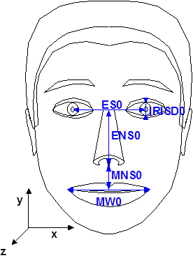
A face object is a digital representation of a human face intended for portraying the facial
expression of a real of imaginary person while it moves e.g. as a consequence of his speaking activity. A face object is animated by a stream of face animation parameters (FAP) encoded
at low bitrate. The FAPs control key feature points in a mesh model of the face to produce
animated visemes for the mouth (lips, tongue, teeth), as well as animation of the head and facial features like the eyes. A face model can also be manipulated at the receiving end.
It is possible to animate a default face model in the receiver with a stream of FAPs or a custom face can be initialized by downloading Face Definition Parametres (FDP) with specific background images, facial textures and head geometry.
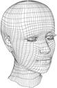
The ‘facial animation object’ can be used to render an animated face. The face object contains a generic face with a neutral expression that can be rendered as is. The shape, texture and expressions of the face are controlled by Facial Definition Parametres (FDP) and/or Facial Animation Parametres (FAP).
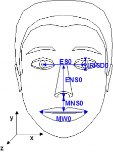
Figure 1 – Face Definition Parametres
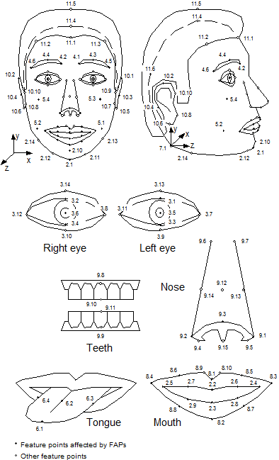
Upon receiving the animation parameters from the bitstream, the face can be animated: expressions, speech, etc. and FDPs can be sent to change the appearance of the face from something generic to a particular face with its own shape and texture. If so desired, a complete face model can be downloaded via the FDP set. However, face models are not mandated by the standard. It is also possible to use specific configurations of the lips and the mood of the speaker.

Figure 2 – Face Animation Parametres
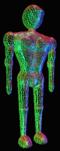
The Body is an object capable of producing virtual body models and animations in the form of a set of 3D polygonal meshes ready for rendering. Here, too, we have two sets of parameters defined for the body: the Body Definition Parametre (BDP) set, and the Body Animation Parametre (BAP) set. The BDP set defines the set of parametres to transform the default body to a customised body with its surface, dimensions, and (optionally) texture. The BAPs will produce reasonably similar high level results in terms of body posture and animation on different body models.
In the area of synthetic audio two important technologies are available. The first is a Text To Speech (TTS) Interface (TTSI), i.e. a standard way to represent prosodic parameters, such as pitch contour, phoneme duration, and so on. Typically these can be used in a proprietary TTS system to improve the synthesised speech quality and to create, with the synthetic face, a complete audio-visual talking face. The TTS can also be synchronised with the facial expressions of an animated talking head as in Figure 3.
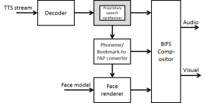
Figure 3 – TTS-driven Face Animation
The second technology provides a rich toolset for creating synthetic sounds and music, called Structured Audio (SA). Newly developed formats to specify synthesis algorithms and their control, any current or future sound-synthesis technique can be used to create and process sound in MPEG-4.
3D Mesh Coding (3DMC) targets the efficient coding of 3D mesh objects, polygonal model that can be represented in BIFS as IndexedFaceSet, a node representing a 3D shape constructed with faces (polygons) from a list of vertices, and Hierarchical 3D Mesh node. It is defined by 1) vertice positions (geometry), 2) face and its sustaining vertices association (connectivity), and optionally by 3) colours, normals and texture coordinates (properties).
3DMC can operate in a basic mode with incremental representations of a single resolution 3D model, and in optional modes: 1) support for computational graceful degradation control; 2) support for non-manifold model; 3) support for error resilience; and 4) quality scalability via hierarchical transmission of levels of detail with implicit support for smooth transition betw
een consecutive levels.
At the Melbourne meeting in October 1999 Euee S. Jang, then with Samsung, took over from Peter to complete FBA and address the important area of 3D mesh compression, in particular efficient encoding of generic 3D model animation framework, later to be called Animation Framework eXtension (AFX) and to become part 16 of MPEG-4. At the Fairfax meeting in March 2002 Mikaël Bourges-Sévenier took over from Euee to continue AFX and develop Part 21 MPEG-J Graphics Framework eXtensions (GFX).
The MPEG-4 Animation Framework eXtension (AFX) — ISO/IEC 14496-16 — contains a set of 3D tools for interactive 3D content operating at the geometry, modeling and biomechanical level and encompassing existing tools previously defined in MPEG-4. The tools available in AFX and related illustrations are summarized in Figure 1.
| Tool name |
Objective |
Example |
| Parametric curve and surface representations |
Delivering smooth shapes with a high level deformation control |
 |
| Subdivision Surfaces |
Simplification and progressive transmission of large scale models |
 |
| MeshGrid Surface |
Representing generic models preserving volume information, and offering versatile manipulation features |
  |
|
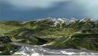
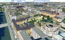
| Footprint Based Representation |
Simplification and progressive transmission of object based on footprints (buildings, cartoons, etc) |
 |
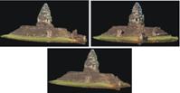
| Depth Image-Based Representation |
3D photorealistic display of objects from a set of images |
 |
| Depth Image-Based Representation Version 2 |
High-quality rendering of image- and point-based objects |
  |
|
| Multi-Texture |
Provide multiple textures for natural appearance together with view-adaptive real-time weighting |
 |
| Morphing space |
Combining bilinear interpolation of several target shapes with a base shape in order to obtain precise deformations and smooth animation |
  |
|
| Solid Modeling |
Combining simple 3D primitives for a compact and exact analytical representation of manufactured and architectural models |
 |
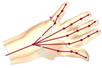
| Deformers |
Enabling controlled non rigid displacements |
 |
| Bone-Based Animation |
Modeling and animation of generic articulated 3D objects |
  |
|
Figure 4 AFX tools
At the Hong Kong meeting in January 2005 Mahnjin Han took over from Mikaël especially to continue the AFX activity.
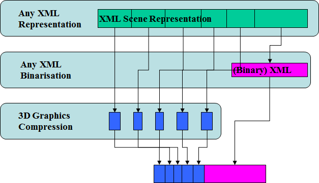
At the Marrakesh meeting in January 2007 Marius Preda took over from Mahnjin. Besides continuing the AFX activity Marius proposed a new area of work called 3D Graphics Compression Model with the goal of specifying an architectural model able to accommodate third-party XML based description of scene graph and graphics primitives, possibly with binarisation tools and with MPEG-4 3D Graphics Compression tools specified in MPEG-4 part 2, 11 and 16.
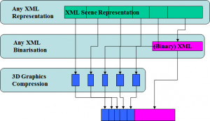
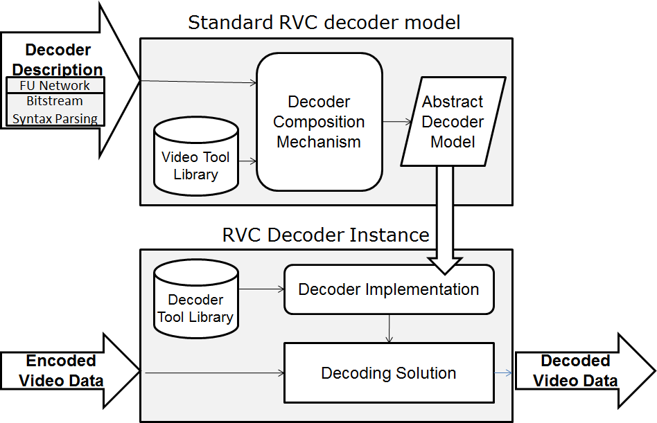
Figure 5 – 3DG Compression Model
This layers of this architecture are (numbering from the low layer)
- Layer 3: any scene graph and graphics primitive representation formalism expressed in XML
- Layer 2: the binarised version of the XML data not encoded by the MPEG-4 elementary bitstreams encoders (e.g. scene graph elements), encapsulated in the “meta” atom of the MP4 file
- Layer 1: a range of compression tools from MPEG-4 part 11 and 16