Protecting Rights

The MPEG-1 standard was an offspring of its age. Just as CD Audio had no content protection provision  – something the music industry came to regret – the MPEG-1 standard had no content protection provision.

MPEG-2 was a different story. Even without considering subscription-based CATV, pay TV, both on terrestrial and satellite networks, was not unknown in the early 1990s. Most of the pay TV available at that time was good old composite television with some tricks to scramble video and audio. Anybody wanting to watch those programs could subscribe to a Service Provider and receive a special “decoder” to unscramble the signal so that he could watch the TV programs. Some pay TV services using MAC already existed in Europe because this was a well-designed system where video information was analogue (when the design of MAC had started that was the only practical choice), but all the rest of the information, including audio, was (uncompressed) digital and packet-based! In particular it already contained the necessary infrastructure to provide encryption support. 

Pay TV was a major driver for MPEG-2 use. The content protection systems of analogue pay TV were fully proprietary, but the technology was rather simple and STBs not very costly. The same could have been done with MPEG-2, but the pay TV constituency rightly assessed that there would be benefits in adopting a basic standard infrastructure for the clear-text version of the signal. So MPEG-2 Systems provides two types of messages: Entitlement Control Messages (ECM) and Entitlement Management Messages (EMM) that simplify implementation of an encrypted broadcasting service.

In Figure 1 below the payload is first scrambled with a Control Word (CW). The CW is sent scrambled with a Service Key (SK) via an ECM message. The CW is changed with a frequency of about 1 Hz. The SK is scrambled using a user-specific key and sent via an EMM message. As all users must receive a scrambled SK, this information reaches the intended user within a much longer period of time. 

MPEG-2_CP_encoder

Figure 1 – MPEG-2 content protection (encoder)

The recovery of the clear-text information is achieved as indicated in Figure 2 where the scrambled SK is extracted from the EMM message and converted to clear text using the User Key (UK) stored in the receiver’s smart card. In its turn, this descrambles the CW that can eventually be used to descramble the audio-visual payload. This is where MPEG-2 Systems stops. Nothing is said about the nature of the keys, the scrambling algorithms, etc. 

MPEG-2_CP_decoder

Figure 2 – MPEG-2 content protection (decoder)

The DVD encryption system – known as Content Scrambling System – is conceptually similar to the system used for pay TV. The player has a Master Key, which is unique to the DVD player manufacturer and accordingly also known as a Player Key (PK). This is equivalent to the key stored in the smart card inserted in a STB. The player decrypts a Disk Key (DK) that is stored in encrypted form on the DVD disc using its PK. Then the player reads the encrypted Title Key (TK) for the file that it has been asked to play. The TK is needed because a DVD usually contains several files, each with its own TK. The TK is decrypted using the DK. Finally, the decrypted TK is used to descramble the actual content.

DVD_CP

Figure 3 – Content Protection in DVD

Because of the way encryption support is defined, MPEG-2 provides a standard technology that is universally interoperable when used in clear-text, but encrypted transmission is Service Provider-specific. If I am an End User I have an obvious service requirement: if I am only subscribed to SP A, I should not be able to watch the offer of SP B, unless I decide to subscribe with SP B. In the early digital television days, two STBs had to be stacked, but this was not (should not be) a requirement.

This situation was inconvenient to both SP and subscriber. SP needed to find a manufacturer of STBs and make a deal with a security technology provider. The two parties worked together to provide STBs to the SP who then has to purchase the STBs and then subsidise their deployment, the largest cost factor in the SP’s accounts after content itself. The advantage for the SP was the creation of a barrier to the entry of other SPs in the subscriber’s home. The subscriber was inconvenienced because he had to stack as many boxes as there were SPs whose offers he wanted to watch. This was all the more irrational if one thinks that possibly 95% of the electronics in all the boxes is functionally the same. Duplication of STB was needed only because of that security-related 5%. 

One way to alleviate this problem was to use the same STB to watch different SPs who had an agreement to provide common access to their combined services, as in the figure below

simulcrypt

Figure 4 – Simulcrypt (SP1 and SP2)

With “Simulcrypt”, as the system is called, SP1 and SP2 send EMM messages (dotted lines) to the combined set of their subscribers, so that encrypted content (full lines) from both SP1 and SP2 can be viewed by subscribers of both SPs. This requires that the encrypted SK be sent using the UKs of both SPs. The system only works if the two SPs share their subscriber databases, hardly something SPs are willing to do because subscribers are the core asset of their business, unless the SPs are two in name but one in practice. 

Some bolder attempts were made to decouple MPEG-2 decoding from access control.

CA0-CA1

Figure 5 – The DVB and DAVIC approaches to “more open” content protection

In the figure, the CA0 interface, defined by DVB and called Common Interface (CI), is simply an interface where an external, SP-specific, box is plugged: scrambled streams enter the box and leave the box as clear-text. STB’s with CI are expensive and the external device is also expensive because of the high-speed electronics. Further, the clear-text program crosses the SI and can be easily tapped. The CA1 interface, defined by DAVIC, was more elaborate, with low bitrate ECM and EMM signals entering an external device (a smart card) and the control word entering the STB. The DAVIC solution would not suffer from the shortcomings of CI because it only handled the low bitrate EMM and ECM messages and did not provide access to clear-text signals, but required some form of standardisation that SPs were loath to accept. 

Another solution that took root in several countries was to embed all Conditional Access (CA) technologies used in a country for Digital Terrestrial Broadcasting in one set top box. Practical as it may appear, this solution ratifies the existence of a security technology club where it would be hard for a new security company to enter.

Several years ago, European regulators did not perceive the apparent contradiction when they mandated, in one of their directives, the use of MPEG-2 for source coding and multiplexing but remained silent about the Conditional Access (CA) part. Much as I am flattered by the idea that the use of MPEG-2 was made legally binding in Europe if somebody wants to broadcast, I cannot help but wonder about the meaning of such an imposition. If the STB is proprietary because of CA, so could be source coding and multiplexing. Why should there ever have been a directive? On the other hand the subsequent creation of monopolies in information provision was swallowed without a gulp. 

I may be the only one, but I am in desperate need for an explanation of what is the meaning and purpose of regulation and competition in this domain.


Computer Programming

Electronic computers were a great invention indeed and the progress of the hardware that has enabled the building of machines that get smaller and smaller year after year while, at the same time, they get more powerful in processing data, has been and continues to be astonishing. In 80 years we have moved from machines whose size and weight were measured in cubic metres and tons (the first ENIAC weighed more than 30 tons) and needed special air-conditioned rooms, to devices that can be measured in cubic millimetres and grams and can be found in cars, domestic appliances or are even worn by people. At the same time the ability to process data has improved by many orders of magnitude. 

eniac

Figure 1 – A corner of the ENIAC computer

Unlike most other machines that can be used as soon as they are physically available, however, before one can use a computer for a purpose one must prepare a set of instructions (a “program”). This may be easy to do if the program is simple, but may require a major effort if the program involves a long series of instructions with branching points that depend on the state of the machine, its environment and user input. Today there are programs of such a complexity that just the cost of developing them can only be adequately measured in hundreds of million if not billions USD.

So, from the early days of the electronic computer age, writing programs has invariably been a very laborious process. In the early years, when computers were programmed using so-called “machine language”, particular training was required because programs consisted entirely of numbers that had to be remembered and written by a very skilled programmer. This was so awkward that it prompted the early replacement of machine language with “assembly language”, with the same structure and command set of a machine language, but with the possibility to use names expressed by characters to represent instructions and variables instead of numbers. As a result, long binary codes, difficult to remember and decode, could be replaced by mnemonic programming codes. 

New “high-level” programming languages, such as COBOL, FORTRAN, Pascal, C, and C++ were developed after assembly languages. These not only enabled computer programming in a language that was more similar to a natural language, but were to a large extent independent of the particular type of computer and could therefore be used, possibly with minor adaptations, on other computers. Of course every type of computer had to have a “compiler”, i.e. a specially designed program capable of converting the program’s “high-level” instructions into a program written in machine or assembly language specific of the environment.

Because of the very high demand for programs from a variety of application domains and the long development times that increasing customer demands placed on developers, there has always been a strong incentive to improve the effectiveness of computer programming. One way to achieve this was through the splitting of monolithic programs into blocks of instructions called “modules” (also called routines, functions, procedures, etc.). These could be independently developed and even become “general purpose”, i.e. they could be written in a way that would allow re-use in other programs to perform a specific function. Using modules, a long and unwieldy program could become a slim and readable “main” (program) that just made “calls” to such modules. Obviously, a call had to specify the module name and in most cases the call to a module contained the parameters, both input and output, that were passed between calling program and module, and vice-versa. Each module could be “compiled”, i.e. converted to machine language, for a particular computer type and combined with the program at the time of “linking”. 

An often obvious classification of modules is between “system level” and “application level”. The former type of module is so called because their purpose is more generic, say, to get data from a keyboard, print a line of text on an output device, etc. The latter type of module is so called because its purpose is more application specific.

From very early on, the collection of “system level” routines was called an Operating System (OS). At the beginning, an OS was a small collection of very basic routines. These were obviously specific to the architecture, maker and model of the computer and were written entirely in assembly language. In fact the low processing power of the CPUs of that time made optimisation of execution an issue of primary importance. As a consequence, the hardware vendor usually supplied the OS with the machine. Later on, OSs became very large with support of advanced features, such as time-sharing, that were offered even with small (for that time) machines, like minicomputers. The importance of the OS and related programs grew constantly over time and, already in the 1970s, machines were often selected more for the features of the OS than for the hardware. 

A major evolution took place in the 1970s, when the Bell Labs developed a general purpose OS called UNIX. The intention was to make an OS that would overcome the tight dependence of the OS on the machine that had prevailed until that time. That dependence could be reduced, however, but not eliminated. A natural solution was to split the OS in two: the first part (“lower” in an obvious hierarchy, starting from the hardware) was called “kernel” and contained instructions that were specific to the computer, the second “higher” part was “generic” and could be used in any computing environment. Such a rational solution quickly made UNIX popular and its use spread widely, particularly in the academic environment. Early UNIX support of networking functions and in particular of the Internet Protocol (IP) was beneficial for the adoption of both the internet and UNIX. Several variations of UNIX appeared. An imporant one is Linux, an Open Source re-writing of UNIX started by Linus Thorvalds. 

In 1975 William Gates III, then aged 19, dropped out of Harvard and founded a company called Microsoft with his friend Paul Allen. They wrote a version of the BASIC programming language for the Altair 8800 microcomputer and put it on the market. In 1980, IBM needed an OS for its PC whose design was progressing fast. After trying with Digital Research, an established software company that owned Control Program for Microcomputers (CP/M), then a well-known OS in PCs of various makes, IBM selected the minuscule (at that time) Microsoft that claimed they could provide develop an operating system for its PC. As he did not have an OS ready, Gates bought, all the rights to 86-DOS, an OS for the Intel 8080 written by Seattle Computer Products for 50,000 USD, rewrote it, named it DOS and licensed it to IBM. Gates obtained from his valued customer the right to retain ownership of what was to become known as Microsoft Disk Operating Systems (MS-DOS), a move that allowed him to control the evolution of the most important PC OS. MS-DOS evolved though different versions (2.11 being the most used for some time in the mid-1980s). 

In 1995, after some 10 years of development, Microsoft released Windows 95, in which MS-DOS ceased to be the OS “kernel” and became available, for users who still needed it, only as a special program running under the new OS. Another OS started by Microsoft without MS-DOS backward compatibility constraints of Windows 95 and called New Technology (NT), was later given the same user interface as Windows 95, thereby becoming indistinguishable to the user. Other OSs of the same family were Windows 98 (based on Windows 95), Windows 2000 and Windows XP (both based on Windows NT), Vista, Windows 7, Windows 8, Windows 10, and the current Windows 11. Microsoft also developed a special version of Windows, called Windows CE, for resource-constrained devices and Windows Mobile for mobile devices like cell phones.

A different approach was taken by Sun Microsystems (now part of Oracle) in the first half of the 1990s when it became clear that IT for the CE domain could not be based on the paradigms that had ruled for the previous 50 years of IT, because application programs had to run on different machines. Sun defined a Virtual Machine (VM), i.e. an instruction set for a virtual processor, with a set of libraries that provided services for the execution environment, and called this “Java”. Different profiles of libraries were defined so that Java could be run in environments with different capabilities and requirements. Java became the early choice for program execution in the web browser, but was gradually displaced by a scripting language called ECMA Script (aka Javascript).

The situation described above provides the opportunity to check once more the validity of another of the holy cows of market-driven technology, i.e. that competition makes technology progress. In this general form the statement may be true or untrue and may be relevant or irrelevant. Linux is basically the rewriting of an OS that was designed 50 years ago and is now finding more and more application in Android. Windows was able to achieve today’s performance and stability thanks to the revenues from the MS-DOS franchise that let the company invest in a new OS for 10 years and keep on doing so for many more yearsyears. 

The problem I have with the statement “competition makes technology progress” lies with the unqualified “let competition work” policy, because this forces people to compete on every single element of the technology, leads to a gigantic dispersion of resources because every competitor has to develop all the elements of the technology platform from scratch, actually reduces the number of entities that can participate in the competition, thus excluding potentially valid competitors and eventually produces an outcome of a quality that is not comparable with the (global) investment. Therefore, unless a company has huge economic possibilities, like IBM used to have in hardware, Microsoft has in software and Apple has in hardware and software, and Google has in software, it can perfect no or very few aspects of them. The result is then a set of poor solutions that the market is forced to accept. Users – those who eventually foot the software development bill – are the ones that fund its evolution. There is progress, but at a snail pace, and confined to very few people. Eventually, as the PC OS case shows, the market finds itself largely locked into a single solution controlled by one company. The solution may eventually be good (as a PC user for 40 years, I can attest that it is or – better – that it used to be good for some time), but at what cost! 

Rationality would instead suggest that some basic elements of the technology platform – obviously to be defined on a case-by-case – should be jointly designed so that a level playing field is created on which companies can compete in the provision of good solutions for the benefit of their customers without having to support expensive developments that do not provide a significant added value, distract resources from achieving the goals that matter and result in an unjustified economic burden to end users. 

With the maturing of the business of application program development, it was quite natural that such programs would start being classified as “low level”, such as a compiler and “high level”. Writing programs became more and more sophisticated and new program development methodologies were needed. 

The modularisation approach described above represented the “procedural” approach to programming because the focus was on the “procedures” that had to be “called” in order to solve a particular problem. Structured programming, instead, had the goal of ensuring that the structure of a program helped a programmer understand what the program does. A program is structured if the control flow through the program is evident from the syntactic structure of the program. As an example, structured programming inhibits use of “GOTO” a typical instruction that is used to branch a program depending on the outcome of a certain event, and one that typically makes the program less understandable. 

A further evolution in programming was achieved towards the mid 1980s with object orientation. An “object” is a self-contained piece of software consisting of both the data as well as the procedures needed to manipulate the data. Objects are built using a specific programming language for a specific execution environment. Object oriented programming is an effective methodology because programmers can create new objects that inherit some of their features from existing objects, again under the condition that they are for the particular programming language and the particular execution environment. 

After OSI, a new universality devil – objects – struck the IT world again. Yet another general architecture was conceived by the Object Management Group (OMG) – the Common Object Request Broker Architecture (CORBA). The intention behind this architecture was to enable objects to communicate with one another regardless of the programming language used to write them and the operating system they were running on, and included object location and host hardware. This functionality had to be provided by an Object Request Broker (ORB), a middleware (a software layer) that manages communication and data exchange between objects and allows a client to request a service without knowing anything about what servers are attached to the network. The various ORBs receive the requests, forward them to the appropriate servers, and then hand the results back to the client. 

Since CORBA does not look inside objects because it deals with the interfaces, it needs a language to specify interfaces. The OMG developed Interface Definition Language (IDL), a special object oriented language that programmers can use to specify interfaces. CORBA allows the use of different programming languages for clients and objects, which can execute on different hardware and operating systems, and the clients and objects cannot detect these details about each other.

It clearly seems like a programmer’s dream come true: you keep on living in the (dream) world you have created for yourself and somebody else will benevolently take care of smoothing out the differences between yours and other people’s (dream) worlds. 

The reality, however, is quite different. A successful exploitation of the CORBA concepts could be found in Sun’s Remote Method Invocation (RMI). This enabled Java objects to communicate remotely with other Java objects, but not with other objects. Microsoft with its Component Object Model (COM) and Distributed Component Object Model (DCOM) created another successful exploitation of CORBA concepts for any programming language, but only in the Windows environment, where programmers could develop objects that can be accessed by any COM-compliant applications distributed across a network. The general implementation of the CORBA model, however, found it much harder to make practical inroads. 

CORBA is, after OSI, another attempt at solving a problem that cannot be solved because of the way the IT world operates. To reap the benefits of communication, people must renounce some freedom (remember my definition of standard) to choose programming and execution environments. If no one agrees to cede part of his freedom, all the complexity is put in some magical central function that performs all the necessary translation. Indeed, yet another OSI dream… 

Of course if this does not happen it is not because IT people are dull (they are smart indeed), but because doing things any differently than the way they do would make proprietary systems talk to one another. And this is exactly what IT vendors have no intention of doing.

Going back to my group at CSELT, a big investment was made in CORBA when we developed the ARMIDA platform because the User-to-User part of the DSM-CC protocol is based on it. That experience prompted me to try and do something in this area that concerned this layer of software called middleware.


Operating System Abstraction

My encounter with IT as a (business) tool for the AV world happened towards the end of the MPEG-2 development and was greatly enhanced by my participation in the DAVIC work. Of course until the time I was doing research myself, I had been a good IT user, but only of computing services, i.e. as a tool to write video coding simulation programs and have it run to produce simulation results. But in my exposure to MPEG and DAVIC I saw how the creation of vertical solutions built on top of proprietary CPU’s and OS’s could not lead to the kind of transparent experience of digital AV applications and services that was the target for myself and, by reflection, DAVIC. This aspect was eventually  addressed by DAVIC 1.0 specification with the adoption of MHEG-5, a computing platform-agnostic, purely declarative (i.e. not dependent on a computing environment) multimedia standard.

But something had to be done for the longer term. During the October 1994 HDTV Workshop in Turin I discussed the idea of a “full software” terminal with Marcel Annegarn of Philips, who had been one of the first members joining the HDTV Workshop Steering Committee, and received positive reactions. So motivated to proceed, I considered that such a project could only succeed if I could bring together a small number of major representatives in the CE, IT and telco spaces to an industrial initiative. As I used to say at that time, the goal could be achieved, if necessary, by bringing together the Devil and the Holy Water (Italian expression), without of course identifying which was the Devil and which was the Holy Water.

In December I had already established contacts, in addition to those already started with Philips, with France Telecom, IBM, Microsoft and Sony. A first meeting was convened at CSELT at the end of January 1995 and the decision made to submit a proposal to the next Call of the Advanced Communication Technologies and Services (ACTS) program of the CEC. The non-European companies were represented by their European research facilities but eventually Microsoft dropped out because at that time they did not have a significant European research force to mobilise.

The project was named Software Open Multi-Media Interactive Terminal (SOMMIT) and the goal stated in the proposal was

To define an open interactive multimedia terminal architecture, application and delivery media independent, that allows a full software implementation.

In the course of the project, the goal was made more precise with the following formulation

To provide an object-oriented library suitable to support the writing of the applications that implement multimedia services

that could be ported to different terminals. 

A specific goal of the SOMMIT project was to provide an architecture that would allow source code portability both at the application level (i.e. the possibility of using the same application for different platforms, with different hardware and OSs) and at the library level (i.e. the possibility of porting the same SOMMIT libraries – on which applications rely – to different platforms). In Figure 1 the code located below the Software Library Portability Interface  (SLPI) line was written in a way that portability to many environments was possible. The SOMMIT API (SAPI) was specified in IDL so that a SOMMIT application could be written using a standard high-level language such as C or C++ that could then be compiled for the target platform on which the SOMMIT library was present. The compilation ensured portability of the application through the generation of different versions of the binary code, one for each target platform. This approach allowed high performance and access to platform resources. 

sommit

Fig. 1 – Subsystems of the SOMMIT library

The project implemented all software modules in the figure and worked hard to show a first demo. Unfortunately, this was achieved only a few months after the major CE companies, at least in Europe, had made up their minds about a solution that provided similar functionalities but at the cost of being dependent on a proprietary solution. The Multimedia Home Platform (MHP) specified by DVB did provide all functionalities that the SOMMIT solution would have offered. Its limited market take up had many causes, but one of them is the fact that it was highly antagonised by some quarters, and SPs and application developers stood at the window for some time and eventually turned their eyes elsewhere.


Humans Interact With Machines

Devising methods to interact with machines and the very act of interacting with them are often endeavours with varying degrees of challenge. Playing a musical instrument may require years of practice, while setting the time on a mechanical wristwatch is rather straightforward. Doing the same on a digital wristwatch may not be as straightforward while changing a program on a TV set is easy, even though setting the programs for the first time may be a challenge. When Video Cassette Recorders (VCR) were a normal CE device, the act of programming the recording time on a VCR had achieved the status of emblem in user unfriendliness. 

Early computers had extremely primitive forms of Human-Machine Interaction (HMI). The first peripherals attached to computers were those needed to input and output data, possibly in the form of programs: paper tape, card readers, teletypewriters and line printers. But more primitive forms of interaction were also used. To boot one of the early Digital Equipment PDP-11 minicomputers, still used at CSELT in the mid 1970s, required the manual introduction, through switches, of a basic sequence of binary instructions. 

pdp1140

Figure 1 – The console of a PDP11/40

At that time, interaction with computers had already considerably improved and was based on a very simple Command Line Interface (CLI). On the PDP-11, the RSX OS had a simple command line structure: a 3-letter code to indicate the function (e.g. PIP – Peripheral Interchange Program, to move files from one device to another) was followed by a sequence of characters specific to the particular function invoked with the first 3 letters. The airline reservation systems, the earliest mainframe query protocols still in use, were developed during that period of time with the goal to stuff as much information as possible into compact commands. 

With CPU power increasing in the 1960s and early 1970s, researchers began to consider new ways to reduce the data entry time and typing errors. In the late 1970s, the microcomputers’ drop in price of computing power resulted in popularisation of computing that later gave rise to the PC. So research was started on the “next generation” of computers because evolving computer interaction from the “vestals” model recalled above, to the “anybody does what he likes with his own PC” model, required substantial changes. 

The most notable interface research was carried out at the Xerox Palo Alto Research Center (PARC) where the Alto computer, completed in 1973, was the first system equipped with all the elements of the modern Graphical User Interface (GUI): 3-button mouse, bit-mapped display and graphical windows. 

The Alto HMI allowed users to have a communication with the computer that was more congenial to humans than before. Visual elements with a graphic content – icons – were introduced because they could be more effectively tracked and processed by the left hemisphere of the brain, unlike characters that require a sophisticated and highly specialised processing by the right hemisphere of the brain because characters represent a highly structured form of information.

Eight years later (1981) Xerox introduced the Star, the commercial version of the Alto computer whose interface added the concept of the desktop metaphor, overlapping and resizable windows, double-clickable icons, dialog boxes and a monochrome display with a resolution of 1024*768, not so far from what we have today on our PC monitor, save for colour and higher resolutions. Unfortunately, Xerox was unable to commercially exploit this innovative development.

Apple Computer was the one that really benefitted from the new HMI. Xerox allowed Apple to take elements of the Star interface in exchange for Apple stocks. Lisa , the first computer with the new HMI released in 1983, flopped and was followed by the Macintosh the following year. This turned out to be a success, through alternate phases. For several years Apple spent millions USD to enhance the Macintosh GUI, a commitment that paid off in the late 1980s when the professional market boomed and Apple’s GUI became an emblem of the new world of personal computing, widely praised and adopted by artists, writers, and publishers. The consistent implementation of user interfaces across applications was another reason for the success of the Macintosh that made Apple, for some time in the early 1990s, the biggest PC manufacturer.

Unlike what could be seen at Xerox and Apple, the IBM PC running MS-DOS had a cryptic Command Line Interface (CLI), but things were evolving. Already in 1983 some application programs like Visi On by Visi Corp, the company that had developed the epoch-marking Visicalc program, had added an integrated graphical software environment. In 1984 Digital Research announced its GEM icon/desktop user interface for MS-DOS, with just two unmovable, non-resizable windows for file browsing, a deliberately crippled version of its original development.

In the second half of the 1980s, Microsoft embarked on the development of a new OS with a different GUI and for some time cooperated with IBM in the development of their new OS, called OS/2, that IBM hoped would be generally adopted by the PC industry. Later, however, the partnership soured and Microsoft went it alone with Windows. At first, the new interface was simply a special MS-DOS application that made available different graphic shells and providing such features as GUI and single-user multitasking. Apple sued Microsoft about the use of the Windows GUI but Microsoft successfully resisted. 

A similar process happened with UNIX. Like MS-DOS, UNIX has an obscure CLI inherited from mainframes. In the 1980s UNIX GUI shells were developed by consortia of workstation manufacturers to make their systems easier to use. The principal GUIs were Solaris by Sun Microsystems and Motif by the Open Software Foundation (OSF). 

With computers taking on many more forms than the traditional workstation or the PC, the HMI became more and more crucial. One major case is provided by mobile handsets where reduced device size puts more constraints on the ability of humans to interact with the range of new services on offer today. The hottest spot was the set of technologies that Apple had assembled for its iPod, iPhone and iPad devices, but parallel developments happened on the rival Android front, as specialised by individual handset manufacturers. Companies endeavoured to emulate – and sometimes were brought to court in a string of apparently never ending legal battles.

It is now some 50 years since the GUI paradigm was first applied, and its use is now ubiquitous. There is a good reason to expect forms of HMI and many interesting components are indeed available such as speech to text, and voice and gesture commands. However, no new paradigm comparable to the one brought forward by Xerox some 50 years ago is on the horizon.


Computers Create Pictures And Sound

Most of what has been said so far concerns audio and visual information generated in the real world and reaching human senses either directly or through a more or less transparent communication system. However, an increasing proportion of what we perceive today through communication devices is no longer generated in that way. Images and sound from computers and game consoles, originally almost exclusively synthetically generated, have an increasing share of naturally generated media, while what we perceive from TV sets and movie theatre screens, originally almost exclusively naturally generated, is more and more complemented by synthetically generated audio and video.

Because of this trend, the laying out of the digital media scene in preparation for the MPEG-4 stage would not be complete without a ride on these other types of bit. Indeed, and complementing its “moving picture” label, MPEG did operate in this space since 1995 trying to build bridges between business communities in disciplines considered specific to them. Purpose of this page is then to clarify the background of synthetically-generated pictures and sound to help understand the role that MPEG had in it.

From the beginning, computers were machines capable of connecting to and controlling all sort of devices and thus ideally suited to replace the infinite number of ad-hoc solutions that for centuries humans had conceived to make a machine respond, in a predictable way, to external stimuli or to generate “events” directly correlated to its internal state. Besides typical “data processing” peripherals like tape and card readers and line printers, over the years computer mice, joysticks, game pads, track balls, plotters, scanners and more were attached to computers. Of more interest for the purpose of this page, however, are other types of device such as microphones-loudspeakers and video cameras-monitors. 

As early as the 1950s, computers were already connected to oscilloscopes used as display devices and in the 1960s direct-view storage tubes were also connected. In 1963, the Bell Labs developed a computer-generated film entitled “Simulation of a two-giro gravity attitude control system”. By the mid-1960’s, major corporations started taking an interest in this field and IBM was the first to make a commercially available graphics terminal (IBM 2250). The unstoppable drive to connecting all sorts of device to computers is well demonstrated by the computer-controlled Head-Mounted Display (HMD) realised in 1966 at MIT. The HMD provided a synthetically-generated stereoscopic 3D view by displaying two separate images, one for each eye. In 1975 Evans & Sutherland developed a frame buffer that could hold a picture. 

In the very same years, after my second return from Japan in October 1973, my group at CSELT developed a 1 Mbyte frame store for video coding simulation built with 16 Kbit RAM chips. It was capable of capturing and storing a few monochrome and composite (PAL) video frames in real time. The video store was interfaced to a GP-16, a simple but effective minicomputer manufactured by Selenia (now Thalès Alenia Space, at that time a company of the STET group) and video samples could be transferred to a magnetic tape and read by a mainframe computer. Video coding algorithms were tested on the mainframe and the processed data were again loaded on a magnetic tape, transferred from tape to RAM and visualised on the simulation system. If one considers that one cycle of this process could take days, it should not be difficulty to understand why I have used the word “vestals” to describe the people running the mainframe computers in those days. 

3D Graphics (3DG) is the name given to the set of computer programming techniques that enable effective generation of realistic 3D images for projection on a 2D surface or rendering in a 3D space.  The impressive evolution of this field is paradigmatic of the way academic interests successfully morphed into commercial exploitation. The development of output devices matched to the needs of synthetic picture viewing was a necessary complement to Computer Graphic’s value. The field evolved in a matter of 15 years through a number of milestones that are briefly sketched in the table below.

Algorithm Description
Hidden-surface Determines which surfaces are “behind” an object and thus should be “hidden” when the computer creates a 2D image representing what of a 3D scene a viewer should see. 
Colour interpolation Improves the realism of the synthetic image by interpolating across the polygons so reducing the aliasing caused by the sharp polygon edges.
Texture Mapping Takes a 2D image of the surface of an object, and then applies it to a 3D object.
Z-buffer Accelerates the hidden surface removal process by storing depth data for every pixel in an image buffer (called Z-buffer because Z represents the depth, Y the vertical position and X the horizontal position). 
Phong shading Interpolates the colours over a polygonal surface with accurate reflective highlights and shading.
Fractal Covers the entire surface of a plane with a curve or geometric figure to create realistic simulations of natural phenomena such as mountains, coastlines, wood grain, etc.
Ray tracing Simulates highly reflective surfaces by a process of tracing every ray of light, starting from the viewer’s perspective back into the 3D scene. In case an object is reflective, the ray is followed as it bounces off the object or until it either hits other objects with an opaque non-reflective surface or leaves the scene. 
Radiosity  Determines how light reflects between surfaces using heat propagation formulae. 

The establishment of commercial companies was made possible by the progress of 3DG technologies and reduced computing price. A milestone was reached in 1988 with the Renderman format. This provided all the information required to render a 3D scene: objects, light sources, cameras, atmospheric effects, etc. 3DG developers could give the modeling system the capability of producing Renderman compatible scene descriptions and output the content on machines supporting the format. In 1990 AutoDesk introduced Studio3D, a 3D computer animation product that achieved a leading position in 3D computer animation software. 

Already in the 1970s, Computer Graphics had entered the world of television and prompted the development of hardware/software systems for scanning and manipulating artwork, e.g. making it squash, stretch, spin, fly around the screen, etc. Morphing, a technique that transforms an image of an object into the image of another object, was first demonstrated in 1983 with a video sequence showing a woman transforming herself into the shape of a lynx. In 1991 massive use of 3DG techniques in movies began with “Toy Story”, the first full-length computer-animated feature film, continuing with “Terminator 2” where the evil T-1000 robot was sometimes Robert Patrick, a real actor, and sometimes a 3D computer animated version. “Beauty and the Beast” contained 3D animated objects, flat shaded with bright colours so that they would blend in with the hand-drawn characters. 

In 1994, a group of companies established a consortium called Virtual Reality Modeling Language (VRML) – now Web3D Consortium – with the goal of developing a standard format to represent 3D worlds. The first specification, issued in 1997 as VRML 97, provided the coded representation of a 3D space that defined most of the commonly used processing types such as hierarchical transformations, light sources, viewpoints, geometry, animation, fog, material properties and texture mapping. 

The need to cater to the growing number of 3DG researcher and user communities prompted the the Association of Computing Machinery (ACM) to establish the Special Interest Group on Computer Graphics (SIGGRAPH). The first SIGGRAPH conference held in 1973 was attended by 1,200 people, but the conference may well have an attendance of tens of thousands of people. 

What has been described so far could be called as the high end of computer graphics, but there is another, originally low- to middle-end application domain, that has given rise to an industry that has used the same computing technologies with an identity of its own: computer games. While the 3DG field had a more traditional evolution – first academia and then exploitation – the computer game field targeted exploitation from the very beginning. With the progress in computing devices, the borders between the two fields blurred. 

This is short tracking shot of this business area in the first decades of its history.

1961 Space War Probably the first video game, said to have been created by an MIT student for the Digital Equipment (DEC) PDP-1. It was very successful and was even used by DEC engineers as a diagnostic program.
1966 Odyssey The first home video game to catch spots of light with manually controlled dots. The game was licensed to Magnavox which sold the game for the consumer market.
1971 Computer Space The first arcade video game based on Space Wars – limited success.
1972 Pong Arcade video game (name from ping-pong) – hugely successful.
1976 Atari (from the name of a move in the Japanese game “go”) is sold to Warner Communication.
1977 2600 VCS Atari introduces the first home game console with multiple games with 2Kbyte of ROM and 128 bytes of RAM.
1978 Space Invaders Taito releases the first blockbuster videogame installed in restaurants and corner stores.
1979 Atari 800 Atari introduces Atari 800, an 9-bit machine.
Space Invaders Translated to the Atari 2600 video home game system.
1979 Activision Is established by Atari developers followed by other third-party development houses in the 1980’s Epyx, Broderbund, Sierra On-Line and SSI.
1980  Odyssey2 Philips releases the game. This is followed by Intellivision (Mattel) and Pac-Man  (Namco). More than 300,000 arcade units sold since introduction, a huge hit and an unforgettable experience of many no-longer-so-young people who have been raised in an environment populated by such computer game names, such as Zork, Donkey Kong, Galaxian, Centipede, Tempest, Ms. Pac-Man and Choplifter!).
1981 Dozens of games for home computers such as Apple, Atari, and TRS-80 released.
1981 The game industry is worth more than 6 B$ in sales. Atari alone does 1B$ with Asteroids throughout its life span.
1982 Gaming companies still producing hits such as Access Software, Electronic Arts, and Lucasfilm Games (now LucasArts) are established.
Olympic Decathlon Microsoft publishes this not particularly successful game, one reason why it took years before Microsoft would publish another computer game.
1st half of 1980s Home computers with game capabilities released: Atari 400 and 800, Commodore VIC-20 and C-64 (20 million units sold in 1982 when it was released). Common features: colour display capabilities, composite video output for TV sets, tape units, floppy disk drives and cartridge.
1981 CGA IBM releases Colour Graphic Adaptor, the first PC colour video adaptor with 4 colours.
1984 Cartridge-based systems become unpopular, video game industry loses ground, home computers (Commodore et al.) gain ground because of the possibility to do more than games.
1985 C-64 Outsells Apple’s and Atari’s computers.
Amiga Launched with many advanced graphic features – another unforgettable experience.
Nintendo Nintendo Entertainment System (NES) is characterised by strict control on software, lockout chip, and restriction to companies to 5 games/year.
TARGA ATT releases the first board for PC professional applications, capable of displaying 32 colours.
1986 Sega Sega Master System console, technically superior to Nintendo, but a market failure because of lack of games caused by Sega’s neglect of third-party developers.
1988 Sierra On-Line Uses the 16-colour Enhanced Graphic Adaptor (EGA) graphics.
1989 Genesis 16-bit console with Electronic Arts sports titles. Nintendo keeps its 8-bits. Nintendo releases Super Mario 3 (all-time best-seller), Amiga and Atari ST die out.
The first game using the 256-colour Video Graphic Adaptor (VGA) graphics is published.
1991 Super-NES Nintendo launches a 16-bit console.
1992 Nintendo 7 billion USD in sales and higher profits than all U.S. movie and TV studios combined. 
PC gaming explodes.
1993 Real Panasonic ships the 32-bit console from 3DO.
Sega and Nintendo consoles held 80% of the game market.
1994 Jaguar Atari ships the 64-bit console.
1995 Saturn Sega ships the 32-bit console.
Playstation Sony ships the 32-bit console.
Window 95 Microsoft releases the new OS  that included the Game SDK – Direct-X thus bringing major game performance under the folds of Windows.
1996 Ultra 64 Nintendo ships the 64-bit console.
Internet boosts the growth of multi-player gaming.
1997 3D-FX 3D acceleration starts to standardise and 3D acceleration became a common game feature.
Pentium II at 200 MHz starts providing serious game experiences.
1998 Many very good PC games appeare. Playstation rules in the console domain. Commonality of the movies and gaming businesses: 300 games/year released but only 30 making money and 5 B$ in PC games, about the movie industry’s size.

It took a considerable amount of time for computers of reasonable cost to provide a video output because of two heavy requirements on computers: fast CPUs to process a high amount of data and a large memory because of the need to store at least one screenful of data that could be generated asynchronously by the CPU and read out synchronously and converted to analogue form to drive a display. 

For audio, matters were much simpler because waveforms could easily be generated in real time or read from a file on a disk, and converted to analogue form to drive a loudspeaker. If the waveform corresponded to a musical score, it was rather easy to provide special hardware designed to produce different types of sound. As an example, the C-64 had a built-in analog synthesiser chip and many games had an obsessive tune accompanying the game that changed depending on the state of the game. In 1989 the first sound cards, the Adlib and Soundblaster, brought a more professional sound to the PC, replacing the original “beep” of the internal speaker. 

The Musical Instrument Digital Interface (MIDI), developed in 1983 by Sequential Circuits and Roland, is a protocol to control electronic musical devices. A MIDI message can tell a synthesiser when to start and stop playing a specific note, the volume of the note, the aftertouch (the amount of pressure applied on the keys of a given channel), the instrument desired to play on a channel, how to change sounds, master volume, modulation devices, and even how to receive information. In more advanced uses, MIDI information can indicate the starting and stopping points of a song or the metric position within a song. 


Internet and the World Wide Web

Today the word “Internet” has become an integral part of everyone’s everyday vocabulary. So it is understandable that many people, with grounds or without, claim to have had a role in their development. I firmly claim to have had no role in the development of either. At the time I started MPEG, and for many years afterwards, I had limited knowledge of what was happening in the environment that we loosely call “internet ” even though for many years I had been a good user of some of their products, namely File Transfer Protocol (FTP) and Simple Mail Transport Protocol (SMTP, aka electronic mail). 

So a reader could very well ask why this page should even appear in the Riding the Media Bits series. One answer is that the internet is an interesting and paradigmatic success story there is much to learn from. It is a good example of how outstanding results can be produced when – as it happened for the internet – Public Authorities invest in R&D targeted for an appropriate time frame, with measurable concrete benefits for the funding authority, and the funding measures are complemented by proper links between industry and the environments carrying out the research. 

The internet project is also an example of the complete life cycle of a research program: it started from technological roots and created an industry capable of producing the pieces of infrastructure needed by the project; then it actually deployed the network; a broad community of users had its hands in the network and continued the collaborative development of the specifications and at the same time field tested them. The growing size of the infrastructure being deployed required operation and management and a form of “standardisation” (the people involved in the internet venture may not like this term, but I think they would they would if they knew my definition of standard), the latter also taking care of the constant evolution of the technology. Lastly, the project is remarkable because it yielded an effective transition from R&D into a commercially exploitable venture that has provided considerable benefits to the country that initiated and, for all practical purposes, has managed so far its operation.

The second answer is that, with a hindsight and without hiding the differences, some superficial, some more deep-rooted, it turns out that there are striking similarities between many of the ideas that have guided the developments of the internet and MPEG. The third, and quite relevant, answer is that the internet is going to play an increasingly important role as a communication infrastructure and the interactions with MPEG standards. 

The following is a brief account of the history of the internet and of the World Wide Web assembled from publicly available information. I have tried to filter out the inevitable lore that has sprouted from a venture of such an impact on people’s imagination, and I apologise for any error that knowledgeable readers may find in this page. This may have been caused either by the inaccuracy of my sources or my misreading of them or my excessive filtering or by all the three causes together. 

Here is an approximately sequential list of events.

1957 ARPA The Advanced Research Projects Agency, an agency of the Department of Defence (DoD), with the purpose of establishing a US lead in science and technology applicable to the military, is established after the US government discovers that the USSR has launched their man-made Sputnik satellite around the Earth leaving the US behind in the race to space. ARPA research projects cover electronic computing and some of the first projects were about war game scenarios, timesharing and computer languages. Computer graphics, another project area, spurred the progress made in the 3DG domain reported before.
2nd half of 1960s IMP The idea of linking computers via the network takes shape. Basic technologies are: a protocol for computer-to-computer communication and the intelligence for other computers – “hosts” – to route data packets using a packet switching technique. Interface Message Processor (IMP) was the name given to these special hosts making up the “ARPANET” computer network
1969 The first IMPs are installed at four universities across the USA and more added in 1970. They are linked by “high speed” lines of 56 kbit/s to the site of the Bolt, Beranek and Newman (BBN) manufacturer. The typical use of the network was remote login (Telnet), i.e. the use of computing resources via remote terminals
1970 NCP (December) Network Control Protocol, the first ARPANET Host-to-Host protocol is completed making it possible to develop application protocols on top of it, e.g. FTP and electronic mail following soon after. Electronic mail included such functionalities as listing, selecting, reading, filing, forwarding, and responding to messages. The NCP relied on the ARPANET to provide end-to-end flow control, the set of services that included packet reordering and lost packet recovery. These functions were not provided by other networks, such as SATNET (satellite networking) and packet radio.
1971 A new IMP is developed that can support up to 63 terminals simultaneously connected, overcoming the original limitation of a maximum of four terminals at a time.
TCP Work starts to develop the Transmission-Control Protocol to connect different network
1977 Interconnection is demonstrated by moving data between ARPANET, SATNET and the packet radio network: data is sent from San Francisco to London and back to California travelling 150,000 km without losing a bit. The name Internet comes from the idea of a protocol capable of overcoming barriers between different networks.
1978 TCP is split into two separate functions: 1) TCP proper, performing the function of breaking up the datagrams and reassembling them at the destination, executing flow control and recovering from lost packets, 2) IP, performing the addressing and forwarding of individual packets. This functionality split, an obvious one after the rationalisation made by OSI, was necessary because computer-to-computer communication required flow control and packet-loss recovery, while in real-time communication, e.g. in human-to-human voice communication, a packet loss may be preferable to waiting possibly for a long time for the desired packet to arrive.
1979 ICCB ARPA established the Internet Configuration Control Board
The requirements of the two communication forms that utilise the same packet-based data communication technology signal another difference: Computer-oriented data communication provides errorless transmissions, no matter how long it may take, because in general computers do not know how to deal with errors, but human-oriented communication is fast but does not guarantee errorless transmission, because humans hate to wait but have some capability of making up for missing or damaged information. Indeed, one of the major differentiating factors between different MPEG-2 decoders is the different ability to minimise the visual and audio effects by recovering transmission errors.
1983 (1st of January) ARPANET adopts the new protocol. This date can be taken to be the official birth date of the Internet.
IAB ICCB is replaced by the Internet Activities Board. Under the IAB several Task Forces are created, in particular the Internet Engineering Task Force (IETF) manages the technical evolution of the Internet. Later, WGs were combined into Areas under the responsibility of Area Directors. The Internet Engineering Steering Group (IESG) is composed of the Area Directors. Today tens of WGs are active in the IETF.
1984 DNS The Domain Name System is developed with the goal of translating the domain name expressed in characters, e.g. chiariglione.org, into an IP number. The Internet Corporation for Assigned Names and Numbers (ICANN) oversees the distribution of unique numeric IP addresses and domain names and is responsible for managing and coordinating the DNS to ensure the correct translation of a name into its IP address, also called “universal resolvability”. The DNS is based on 13 special computers distributed around the world, called root servers, coordinated by ICANN. These contain the same information, so that it is possible to spread the workload and back each other up. The root servers contain the IP addresses of all the Top Level Domain (TLD) registries – i.e. the global registries such as .com, .org, etc. and the 244 country-specific registries such as .it (Italy), .br (Brazil), etc. In addition to these, there are thousands of computers – called Domain Name Resolvers (DNR) – that constantly download and copy the information contained in the root servers
1985 The National Science Foundation (NSF) launches a program to establish Internet access across the USA. The backbone was called NSFNET and was open to all educational facilities, academic researchers, government agencies, and international research organizations (CSELT was one of them). As early as 1974, Telenet, a commercial version of ARPANET, had already opened and in 1990 world.std.com became the first commercial provider of Internet dial-up access. Around 1993, Network Solutions took over the job of registering .com domain names.
1991 The Internet Society is established under the auspices of the Corporation for National Research Initiatives (CNRI) of Bob Kahn and the leadership of Vinton Cerf, both major contributors to the early development of the Internet.
1992 IAB The Internet Activities Board becomes the Internet Architecture Board operating under the auspices of the Internet Society
1989 DARPA (the new name that ARPA took when it got a “Defense” at the beginning) pulls the plug on the 22-year old network.

ARPANET and then the Internet set up a huge infrastructure based on sophisticated technologies. Free and open access to the basic documents, especially the specifications of the protocols, was a basic feature of the process. Since the beginnings of the Internet were rooted in the university and research community, the academic tradition of open publication of ideas and results helped make them widely accessible. That was still too slow for a dynamic exchange of ideas and a great innovation was introduced in 1969 with the establishment of the Request for Comments (RFC) series of notes, memos intended to be an informal and fast way to share ideas with other researchers but “standards” for all practical purposes. The first RFCs were printed on paper and distributed via snail mail, but when FTP came into use, RFCs were made available for online access via FTP and this enabled rapid cross-fertilisation: ideas in one RFC triggered more RFCs building on an old RFC. When consensus was achieved, a specification document would be prepared and then used for implementations. 

When DARPA set the internet free, Danny Cohen, another Internet pioneer, said in a speech: 

“In the beginning ARPA created the ARPAnet.
“And the ARPAnet was without form and void.
“And darkness was upon the deep.
“And the spirit of ARPA moved upon the face of the network and ARPA said, ‘Let there be a protocol,’ and there was a protocol. And ARPA saw that it was good.
“And ARPA said, ‘Let there be more protocols,’ and it was so. And ARPA saw that it was good.
“And ARPA said, ‘Let there be more networks,’ and it was so.”
 

I cannot help but add comments to this speech. The part: 

And ARPA said, ‘Let there be more protocols,’ and it was so. And ARPA saw that it was good

would become in MPEG: 

And MPEG said, ‘Let there be more protocols, for new functionalities, and it was so. And MPEG saw that it was good. 

Maybe Danny Cohen meant to say that, but I would not swear he did and the answer can be yes or no depending on some subtleties. Indeed, the practice of the Internet world is one of giving “citizen rights”, i.e. sort of “standard status”, to any new idea that passes peer review. This is an implementation of a Darwinian process applied to ideas, but the survival of an idea depends on people implementing it and using it. Isn’t this great?

Depending on the goal one wants to achieve, this may be a good or a bad idea. If the goal is the goal continuous progress, such as in an academic environment is a good idea because one embeds the seeds of evolution in the system. New ideas improve the old ones and the system becomes better and better. If the seamless use of the infrastructure by the masses is the goal, it is a bad idea because users interested in a service are forced to become experimenters and struggle continuously with instability and disruption in communication. This attitude of the internet world is a direct consequence of the original closed environment of experts building the foundations of the internet carrying out experiments as a day-by-day job. It is not necessarily ideal when there are billions of users who want the system up and running for their own needs and they could not care less about the technicalities of the system or of another technical improvement, unless it is, but only possibly, a major one. 

Instead, the MPEG approach is one of “managed evolution”. Standards are created to solve a communication need using the state of technology at a given time. When progress of technology provided a meaningful quantum step, as assessed by MPEG participants carrying the business needs of their companies, and therefore without affecting the existing millions of users, a new standard was produced and, if necessary, a migration path from the old to the new standard was created.

Continuing my comments on this speech, I would add that, about networks, MPEG had no opinion. As much as there are many roads, rails etc., it is fine if there are many networks. I would even go one step further and say that there could be many transport protocols each designed for a particular goal. But I do not know how many would follow me down this path.

The success of the Internet brought a wind of change in the sleeping telecom and old IT worlds. The hype of computer and telecommunication convergence of the early 1980s had prompted the launch of the ambitious OSI project with strong official support on the part of telecommunication operators, major computer vendors and even governments. By the time the use of the Internet and of the WWW was expanding like wildfire, the OSI project had already been ongoing for 15 years, but the actual product implementation and deployment was still lacking. When products existed, they were available only on large computer installations, while the Internet protocol suite was available on most PCs. 

In a matter of months, the already dwindling support for OSI collapsed. In retrospect, it is clear that the idea to develop a standard allowing a computer of any make (and in the early 1980s there were tens of computers of different makes) to connect to any kind of network, talk to a computer of any make, execute applications on the other computer, etc., no matter how fascinating  and intellectually challenging it was, had very little prospect of success, particularly because this would have forced the opening up of proprietary systems, something that IT vendors had no intention of doing. 

A similar fate, although not as dramatic to the public at large because embedded in the low layers of the network but equally, if not more, disruptive to the executives involved, was awaiting the other major telco standardisation project, Asynchronous Transfer Mode (ATM).

Standardisation had begun in the mid-1980s and had produced several ITU-T recommendations, but in the early 1990s industry was still not making products. Sun Microsystems took the lead and promoted the establishment of a new body called ATM Forum. This had the advantage of having a much wider industry representation and was driven by a much more pragmatic approach to standardisation: facilitating development of standards-based products, not writing specs to satisfy egos. The ATM Forum used to boast that their first specification was developed in just 4 months without any new technical work, just by removing many of the options from existing ITU-T recommendations. Once the option-heavy ITU-T documents that the manufacturing industry, without the backing of fat orders from the telcos, had not dared to implement, became the slim ATM Forum specifications, ATM products became commercially available at the initiative of manufacturers, at interesting prices, and in a matter of months. 

This was not enough to save ATM, though. The prices and volumes that the booming internet infrastructure could command were such that costly ATM equipment could never be competitive. This was one of the causes for the eventual discontinuation of telcos plans to deploy VoD services, which were designed to be based on ATM. ATM was confined to a low layer on top of which IP was used. 

As for all things allowed to have a life of their own, the internet boom has created other problems for the telecommunication equipment manufacturing industry, but that is another story.


Media Meet Computers And Digital Networks

Already in 1991, when MPEG-1 was maturing and the definition of MPEG-2 was rapidly progressing, I had begun to wonder whether there was a scope for work beyond what had been started in 1988, i.e. coding of audio and video for “high” bitrate applications, i.e. above 1 Mbit/s. I triggered some discussions at the Paris MPEG meeting in May 1991 and the rather discounted conclusion was that the lower end of the bitrate spectrum was a likely candidate for such a work. 

That was far from a “new” area for audio and video coding. The ITU-T had been producing a number of speech coding standards aimed at reducing the canonical PCM rate of 64 kbit/s obtained from 8 kHz sampling and 8 bits per sample. Other bodies, like ETSI with GSM, were defining new speech codecs for mobile applications while work had also been done for a so called “wideband speech codec”, i.e. a codec for speech sampled at a rate of 16 kHz and more than 8 bits/sample.  This low bitrate video coding area had also attracted my attention before. In 1987, when I was not as sceptical as today of everything related to person-to-person visual communication, I felt the need to promote ISDN visual telephony because that visual communication field was moving at a snail’s pace. The Picture Coding Symposium (PCS), the recognised forum for video coding studies, had papers on the topic but I thought that by starting the International Workshop on 64 kbit/s coding of moving video and promoting more focused R&D, I could accelerate maturity and eventual deployment of visual telephony on ISDN. The original goal of the H.261 project targeted transmission rates of nx384 kbit/s (384 being the the minimum common denominator between European and American rates of 2048 and 1536, to accommodate the old transmission multiplexing split) when it became clear that 384 kbit/s was too high a transmission speed to be of practical telco interest, but was soon changed to a project for px64 kbit/s coding – where p was allowed to assume any value from 1 to 30 – because ISDN lines with their 128 kbit/s were sitting idle waiting for applications. The ITU-T had even started a new project, called H.263, to develop a video codec to improve the performance of H.261 for the lower bitrates. That was partly because of the new results brought by the insuppressible activity of Gisle Bjøntegaard then of Norwegian Telecom, and because of two announcements of consumer-grade videophones for analogue telephone lines based on proprietary solutions.  All these, however, were initiatives dealing specifically with real-time person-to-person telecommunication applications, the bread and butter of ITU-T, while at that time MPEG had already fully embraced the “generic” approach to media coding standards, aiming at defining the basic coding technology that application domains would then customise for their own specific needs. The domains would certainly include person-to-person communication, but also new opportunities coming from the advancing digital networks, at that time more ATM than the internet, capable of offering on demand entertainment services. The issue of terminals capable of receiving those bitstreams was of lesser concern because the involvement of foot-dragging telco and CE manufacturing was no longer the stumbling block because the PC was an ideal platform because of its opennes and programmability and its widespread deployment. Additionally the advancing digitisation of mobile networks promised by the 3rd Generation (3G) mobile standards provided another opportunity to offer new applications and services. For a few meetings, MPEG kept on discussing the topic and 18 months later had gone a long way in the identification of what it could mean for MPEG to develop a standard in this area. At the SC 29 meeting in November 1992 in Ottawa I presented the proposal for a new project with the title “Very low bitrate audio-visual coding” that was unanimously approved. It took longer than usual for JTC1 to approve the project, but at the July 1993 New York meeting news came that the project had been finally approved. 


MPEG-4 Development

Cliff Reader, who had joined Samsung after leaving Cypress, was appointed as chair of a new AHG with the task of identifying applications and requirements of the new project that had already been christened MPEG-4, before the early dismissal of the MPEG-3 project in July 1992. At the following meeting in September 1993 in Brussels, the ad hoc group was turned into a standing MPEG subgroup with the name of Applications and Operational Environments (AOE). In its 30 months of existence the subgroup was due to generate some of the most innovative ideas that characterise the MPEG-4 standard. 

The original target of the MPEG-4 project was of course another jump in audio and video compression coding. At the beginning there were hopes that model-based coding for video would provide significant improvements, but it was soon realised that what was being obtained by the ITU-T group working on H.263 was probably going to be close to the best performance obtainable by the type of algorithms known as “block-based hybrid DCT/MC” that until then MPEG and ITU-T video coding standards had been based on. For audio, the intention was to be able to cover all types of audio sources, not just music but speech as well, for a very wide range of bitrates. The development of MPEG-2 AAC, barely started at that time, prompted the realisation that AAC could become the “bridge” between the “old” MPEG-1/2 world and the “new” MPEG-4 world. Most of the MPEG-2 AAC development and the entire MPEG-4 version 1 development was led by Peter Schreiner of Scientific Atlanta who was appointed as Audio Chair at the Lausanne meeting in March 1995.

At the Grimstad meeting in July 1994, the scope of the project was reassessed and the conclusion was reached that MPEG-4 should provide support to an extended range of features beyond compression. These were grouped in three categories:

  1. Content-based interactivity, i.e. the ability to interact with units of content inside the content itself.
  2. Compression.
  3. Universal access, including robustness to errors, and scalability. 

While the development of requirements was progressing, I came to realise that MPEG-4 should not just be yet another standard that would accommodate more requirements for more applications than in the past. MPEG-4 should allow more flexibility than had been possible before to configure the compression algorithms. In other words the MPEG-4 standard should extend beyond the definition of complete algorithms to cover coding tools. The alternatives were called “Flex0”, i.e. the traditional monolithic or profile-based standard and “Flex1”, i.e. a standard that could be configured as an assembly of standardised tools. Unfortunately an uninvited guest called “Flex2” joined the party. This represented a standard where algorithms could be defined simply by using an appropriate programming language. 

This was the first real clash between the growing IT and the traditional Signal Processing (SP) technical constituencies within MPEG. The former clearly liked the idea of defining algorithms using a programming language. The decoder could then become a simple programmable machine where a device could download the algorithm used to code the specific piece of content, possibly with the content itself. If practically implementable, Flex2 would have been the ultimate solution to audio and video coding. Unfortunately, this was yet another of the recurring dreams that would never work in practice. “Never”, of course, being defined as “for the foreseeable future”. 

Even if the programming language had been standardised, there would have been no guarantee that the specific implementation using the CPU of the decoder at hand would be able to execute the instructions required by the algorithm in real time. Flex1 was the reasonable compromise whereby the processing-intensive parts would be standardised in the form of coding tools, and could therefore be natively implemented ensuring that standardised tools would be executed in real time. On the other hand, the “control instructions” linking the computationally-intensive parts could withstand the inefficiency of a generic programming language. 

It was not to be so. The computer scientists in MPEG pointed out that a malicious programmer, possibly driven by an even more malicious entrepreneur seeking to break competitors’ decoders, could always make the control part complex enough, e.g. by describing one of the standard tools in the generic programming language, so that any other Flex1 decoder could be made to break. So it was eventually decided that MPEG-4, too, would be another traditional profile-based, monolithic coding standard. 

In the meantime, work on refining the requirements was continuing. The first requirement, i.e. content-based interactivity, is now easy to explain, after years of web-based interactivity. If people like the idea of interacting with text and graphics in a web page, why should they not like to do the same with the individual elements of an audio-visual scene? In order to enable independent access to each element of the scene, e.g. by clicking on them, it would be necessary to have the different audio and visual objects in the scene represented as independent objects. 

Further, at the Tokyo meeting in July 1995 it was realised that this object composition functionality would enable not just the composition of natural but also of synthetic objects in a scene. Therefore MPEG started the so-called Synthetic and Natural Hybrid Coding (SNHC) activity that would eventually produce, among others, the face and body animation, and 3D Mesh Compression (3DMC) parts of the MPEG-4 standard. At the same meeting, the first MPEG-4 CfP was issued. The call sought technologies supporting eight detailed MPEG-4 functionalities. Responses were received by September/October and evaluated partly by subjective tests and partly by experts panels. The video subjective tests were performed in November 1995 at Hughes Aircraft Co., in Los Angeles, while the audio subjective tests were performed in December 1995 at CCETT, Mitsubishi, NTT, and Sony. At the Dallas meeting in November 1995 Laura Contin of CSELT replaced Hidaka-san as the Test Chair.

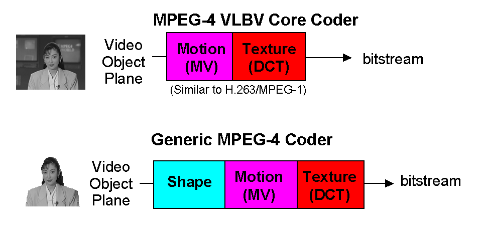
At the Munich meeting in January 1996 the first pieces of the puzzle began to come into place. The MPEG-4 Video Verification Model (VM) was created by taking H.263 as a basis and adding other MPEG-4 specific elements such as the Video Object Plane (VOP), i.e. a plane containing a specific Video Object (VO), possibly of arbitrary shape. At the same meeting the title of the standard was changed to “Coding of audio-visual objects”. Later, other CfPs were issued when new functionalities of the standard required new technologies. This happened over many years for synthetic and hybrid coding tools in July 1996, general call for video and audio in November 1996, identification and protection of content in April 1997, intermedia format in October 1997 and many more to obtain technologies for the 33 parts of the MPEG-4 standard. 

The MPEG-4 Audio work progressed steadily after the tests. Different classes of compression algorithms were considered. For speech, Harmonic Vector eXcitation Coding (HVXC) for a recommended operating bitrate of 2 – 4 kbit/s, and Code Excited Linear Predictive (CELP) coding for an operating bitrate of 4 – 24 kbit/s, For general audio coding at bitrates above 6 kbit/s, transform coding techniques, namely TwinVQ and AAC, were developed.

At the Florence meeting in March 1996, the problem of the MPEG-4 Systems layer came to the fore. In MPEG-1 (and MPEG-2 PS) the Systems layer is truly agnostic of the underlying transport. In the MPEG-2 Transport Stream, the Systems layer includes the transport layer itself. What should be the MPEG-4 Systems layer? Carsten Herpel of Thomson Multimedia, one of the early MPEG members who had represented his company in the COMIS project, was given the task to work on this aspect, making sure that the old Systems experience of previous standards would be carried over to MPEG-4. The problem to be solved was how to describe all the streams, including information such as media, their coding, the bitrate used, etc. as well as the relations between streams, the means to achieve a synchronised presentation of all the streams, that included a timing model and a buffering model for the MPEG-4 terminal. 

The Florence meeting also marked the formal establishment of the Liaison group. Since the very early days of MPEG, I had put particular attention in making the outside world aware of our work, but the management of this “external relations” activity had been dealt with in an ad-hoc fashion. In Florence, I realised that the number and importance of incoming – and hence outgoing – liaison documents had reached the point where MPEG needed a specific function to deal with them on a regular basis. I then asked Barry Haskell of Bell Labs, a key figure in the development of video coding algorithms and the last remaining person, aside from myself, of the original group of 29 attendees at the fist MPEG meeting in Ottawa, to act as chair of the “Liaison group”. Barry played this important role until 2000 when he left his company. His role was taken over by Jan Bormans of IMEC and then by Kate Grant until the dissolution of the group in 2008.

At the Munich meeting in January 1996, Cliff Reader had announced that he would be leaving Samsung and his participation in MPEG was discontinued for the second time. At the Tampere meeting in July 1996, the burgeoning AOE group was split in three parts. The first was the Requirements group that was so reinstated after Sakae Okubo had left MPEG at the Tokyo meeting one year before. The second was the Systems group, which had been chaired by Jan van der Meer since the Lausanne meeting in March 1995 and the third was the SNHC group. The Chairmen of the three groups became Rob Koenen, then with KPN, Olivier Avaro of France Telecom R&D, and Peter Doenges of Evans and Sutherland, respectively. With the replacement of Didier Le Gall by Thomas Sikora of HHI already done in 1995, the new MPEG management team was ready for the new phase of work.

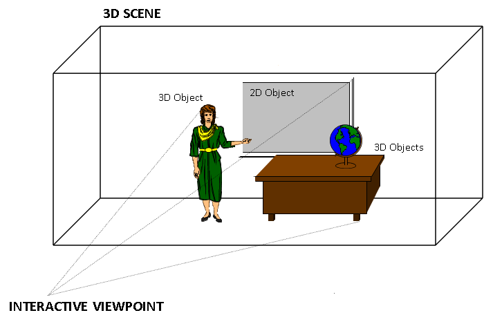
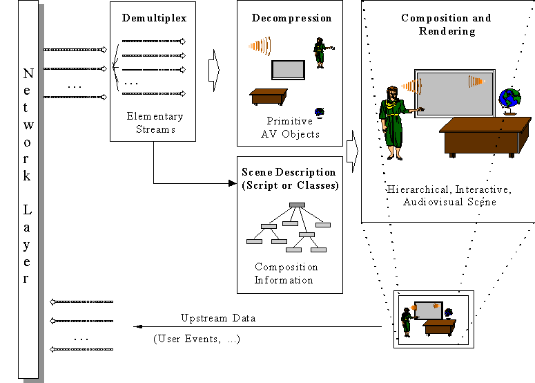
The Systems group needed a new technology not needed in MPEG-1 and MPEG-2 to support the new functionality, namely the ability to “compose” different objects in a scene. The author of a scene needed a composition technology that would tell the decoder where – in a 2D or 3D space – to position the individual audio and visual objects. This would be the MPEG-4 equivalent of the role of a movie director who instructs the scene setter to put a table here and a chair there and asks an actor to enter a room through a door and pronounce a sentence, and another to stop talking and walk away. This “composition” feature was already present in MHEG but was limited to 2D scenes and rectangular objects. 

An MPEG-4 scene could be composed of many objects. The range of object types was quite wide: rectangular video, natural audio, video with shape, synthetic face or body, generic 3D synthetic objects, speech, music, synthetic audio, text, graphics, etc. There could be many ways to compose objects in the visual and sound space. The features to be expressed in spatial composition could be: is this a 2D or a 3D world, where does this object go, in front of or behind this other object, with which transparency and with which mask, does it move, does it react to user input, etc. The features to be expressed in sound composition information could include those just mentioned, but could also include others that are specific to sound, such as room effects. The features to be expressed in a temporal composition could include: the time when an object starts playing, measured relative to the scene, or to another object’s time, etc. 

So there was the need to specify composition directives, these directives being collected in the so-called scene description. MPEG could have defined its own scene composition technology, but that would not have been a wise move. It would have required considerable resources and it would have taken time to have the technology mature enough to be promoted to a standard. More importantly, as we have already mentioned, in early 1997 the Virtual Reality Modeling Language (VRML) of VRML97 was already getting momentum in the 3D Graphics community and, in the best spirit of building bridges between communities and improving interoperability between application areas, it made sense to extend that technology and add the features identified by MPEG-4 requirements, particularly “being compact”, as opposed to VRML file “verbosity”, and “supporting real time media”. 

So, at the February 1997 meeting in Seville, MPEG started the BInary Format for MPEG-4 Scenes (BIFS) activity, led by Julien Signès, then with France Telecom, and subsequently by Jean-Claude Dufourd of ENST. The VRML specification, that had being converted by SC 24 to an ISO/IEC standard as ISO/IEC 14772, was extended to provide such functionalities as 2D composition, the inclusion of streamed audio and video, natural objects, generalised URL, composition update and, most important, compression. 

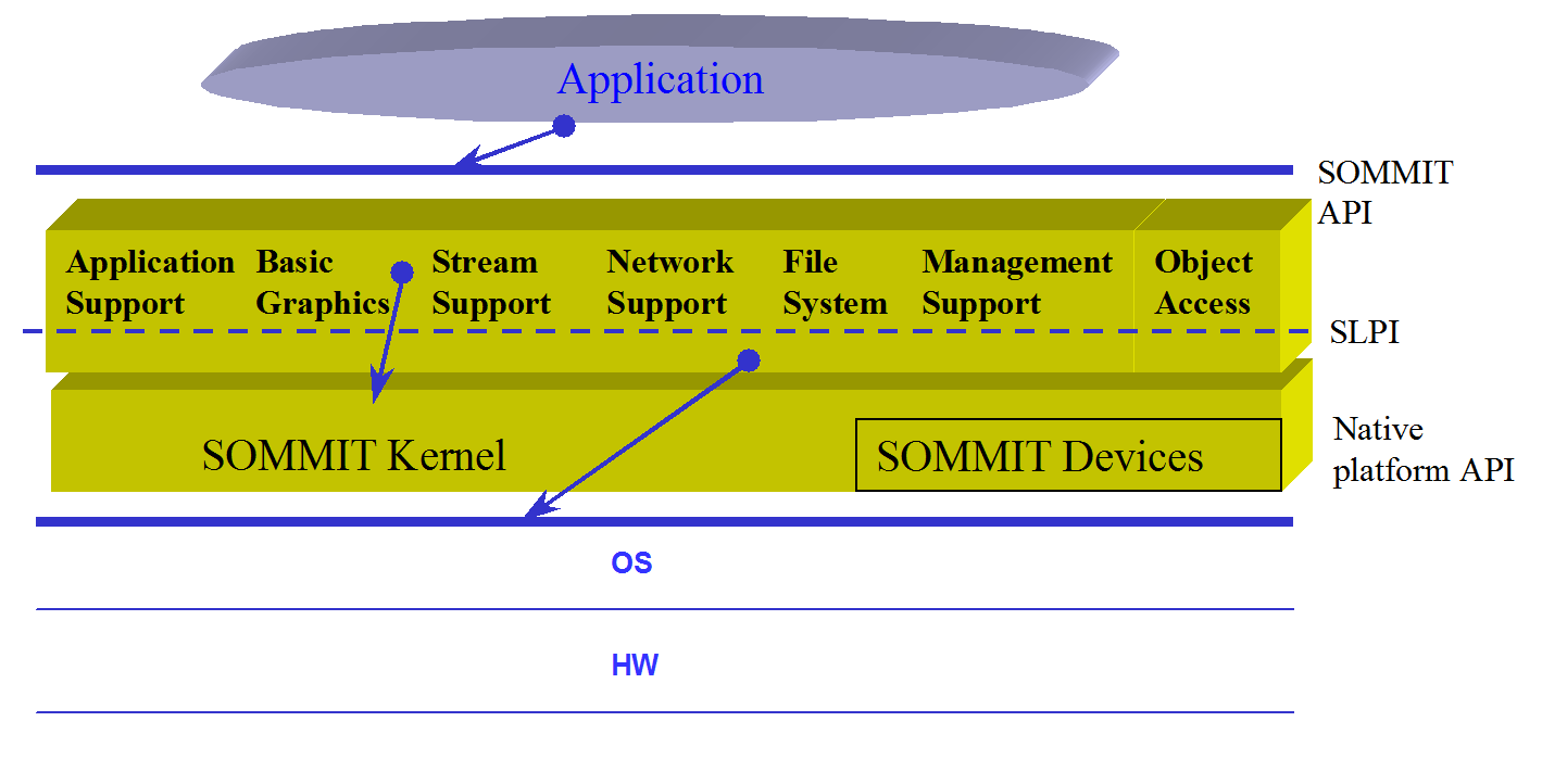
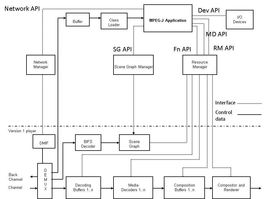
At the time of the Seville meeting, the plan to make an MPEG-4 terminal a programmable device had been abandoned and the decision to use the VRML 97 declarative composition technology was made. Still it was considered useful to have the means to support some programmatic aspects, so that richer applications could become possible. The MHEG group had already selected Java as the technology to enable the expression of programmatic content and the DVB project would adopt Java as the technology for its Multimedia Home Platform (MHP) solution some time later. It was therefore quite natural for MPEG to make a similar choice. MPEG-J was the name given to that programmatic extension. MPEG-J defines a set of Java Application Programming Interfaces (API) to access and control the underlying MPEG-4 terminal that plays an MPEG-4 audio-visual session. Using the MPEG-J APIs, the applications have programmatic access to the scene, network, and decoder resources. In particular it becomes possible to send an MPEG-let (a MPEG-J Application) to the terminal and drive the BIFS decoder directly.

The availability of a composition technology gave new impetus to the SNHC work which defined several key technologies, the most important of which were animation of 2D meshes and Face and Body Animation (FAB). The Vancouver meeting of SNHC (July 1999) was the last chaired by Peter Doenges. At the Melbourne meeting Euee S. Jang, then of Samsung, replaced him and a new piece of work called Animation Framework eXtension (AFX) started to provide an integrated toolbox for building attractive and powerful synthetic MPEG-4 environments.

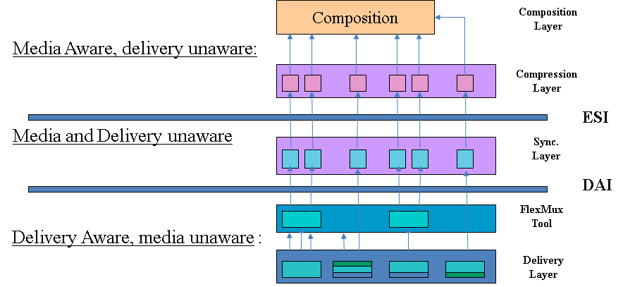
MPEG-4 defines a coded representation of audio-visual content, much as MPEG-1 and MPEG-2. However, the precise way this coded content is moved on the network is to some extent independent of the coded content itself. At the time MPEG-2 was defined, virtually no broadband digital infrastructure existed. Therefore it was decided to define both the coded representation of content and the multiplexing of coded data with signaling information into one serial bitstream. At the time of MPEG-4 development, it became clear that it would not be practical to define a specific solution for content transport, because the available options were – at that time – MPEG-2 TS itself, IP, ATM (a valid option at that time) and H.223, the videoconferencing multiplex of ITU-T. 

Therefore, MPEG decided that, instead of defining yet another transport multiplex, it would specify just the interface between the coded representation of content and the transport for a number of concurrent data streams. But then it became necessary to define some adaptations of the MPEG-4 streams to the other transport protocols, e.g. MPEG-2 TS, so as to enable a synchronised real-time delivery of data streams. 

This included a special type of “transport”, i.e. the one provided by storage. Even though one could envisage the support of different types of formats, an interchange format would provide benefits for content capture, preparation and editing, both locally or from a streaming server. A CfP was issued at the November 1997 meeting in Fribourg (CH), the QuickTime proposal made by Apple with the support of a large number of USA IT companies at the following February 1998 provided the starting point for the so-called MP4 File Format. 

Apart from the file format, MPEG has specified only one other content delivery tool – M4Mux – a simple syntax to interleave data from various streams. Since all relevant delivery stacks support multiplex, usage of this tool was envisaged only in cases where the native multiplex of that delivery mechanism was not flexible enough. 

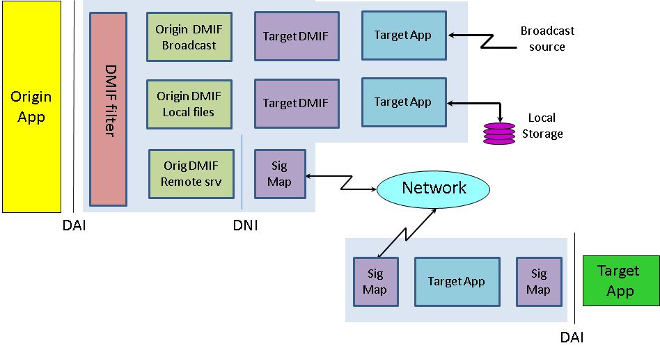
From the very early phases of MPEG-4, MPEG was confronted with the task of providing the equivalent of the MPEG-2 DSM-CC protocol. Most of the people who had developed that standard had left the committee, but not Vahe Balabanian, then with Nortel, who was well known for the piles of contributions he provided at every meeting where DSM-CC was discussed. Vahe came with the proposal to develop a DSM-CC Multimedia Integration Framework (DMIF) and a new group called “DMIF”, where the DSM-CC acronym was replaced by “Delivery”, was established and Vahe was appointed as chairman of that group at the Stockholm meeting in July 1997. 

The idea behind DMIF is that content creators benefit id they could author content in a way that makes it transparent, whether the content is read from a local file or streamed over a two-way network or is received from a one-way channel, such as in broadcast. This is also beneficial to the user because the playback software just needs to be updated with a “DMIF plug in” in order to operate with a new source. The solution was provided by the DMIF Application Interface (DAI), an interface that provides homogeneous access to storage or transport functionalities independently of whether a stream is stored in a file or delivered over the network or received from a satellite source. The December 1998 meeting in Rome was the last Vahe chaired. From the Seoul meeting in March 1999 Guido Franceschini of CSELT took over as chairman. 

Three additional technologies called FlexTime, eXtensible MPEG-4 Textual Format (XMT) and Multiuser Worlds (MUW) were added. The first augments the traditional MPEG-4 timing model to permit synchronization of multiple streams and objects that may originate from multiple sources. The second specifies a representation of the MPEG-4 scene that is textual (as opposed to the BIFS representation that is binary) and its conversion to BIFS. The third technology enables multiple MPEG-4 terminals, sharing an MPEG-4 scene and updating scene changes in all terminals.

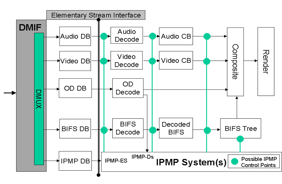
The last major MPEG-4 technology element considered in this chapter is Intellectual Property Management and Protection (IPMP). Giving rights holders the ability to manage and protect their multimedia assets was a necessary condition for acceptance of the MPEG-4 standard. A CfP was issued in April 1997 in Bristol and responses received in July 1997. This part of the standard, developed under the leadership of Niels Rump, then with Fraunhofer Gesellschaft (FhG), led to the definition of “hooks”, hence the terms IPMP Hooks (IPMP-H) allowing the plug in of proprietary protection solutions. 

Another challenge posed by the new environment was the ability to respond to evolving needs, a requirement that MPEG-1 and MPEG-2 did not have. After  its approval, nothing was added to the former and in the first years just some minor enhancements – the 4:2:2 and the Multiview Profiles – were added to MPEG-2 Video. In MPEG-4 it was expected that the number of features to be added would be considerable and therefore the concept of “versions” was introduced. Version 1 of the standard was approved in October 1998 at the Atlantic City, NJ meeting. Version 2 was approved in December 1999 at the Maui, HI meeting. Many other technologies have been added to MPEG-4 such as streaming text and fonts, but these will be presented later.

The development of MPEG-4 continued relentlessly until the dissolution of MPEG. Twenty-five years of efforts yielded a complete repository of multimedia technologies. The following table lists all technology components in the MPEG-4 suite of standards.

1 “Systems” specifies the MPEG-4 Systems layer
2 “Video” specifies MPEG-4 Video
3 “Audio” specifies MPEG-4 Audio
4 “Reference Software” contains the MPEG-4 Reference Software
5 “Conformance” contains MPEG-4 Conformance
6 “Delivery Multimedia Integration Framework” specified the MPEG-4 DMIF
7 “Optimised software for MPEG-4 tools” provides examples of reference software that not just implement the standard correctly but also optimises its performance
8 “4 on IP framework” complements the generic MPEG-4 RTP payload defined by IETF as RFC 3640
9 “Reference Hardware Description” provid “reference software” in Very High Speed Integrated Circuit (VHSIC) Hardware Description Language (VHDL) for synthesis of VLSI chips
10 “Advanced Video Coding” (AVC)
11 “Scene Description” defined Binary Format for MPEG-4 Scenes (BIFS) to “compose” different information elements in a “scene”.
12 ISO Base Media File Format defines a file format to contain timed media information for a presentation in a flexible, extensible format that facilitates interchange, management, editing, and presentation of the media
13 IPMP Extensions extends the IPMP format for additional functionalities
14 “MP4 File Format” extends the File Format to cover the needs of MPEG-4 scenes
15 “AVC File Format” supports the storage of AVC bitstreams and has been later extended to HEVC with the new title “Carriage of NAL unit structured video in the ISO Base Media File Format”
16 Animation Framework eXtension (AFX) defines efficieny coding of shape, texture and animation of interactive synthetic 3D objects. Tools for coding synthetic visual information for 3D graphics are specified in Part 2 – Face and Body Animation and 3D Mesh Compression, Part 11 – Interpolator Compression
17 Streaming Text Format (part 17) defines text streams that are capable of carrying Third Generation Partnership Program (3GPP) Timed Text. To transport the text streams, a flexible framing structure is specified that can be adapted to the various transport layers, such as RTP/UDP/IP and MPEG-2 Transport and Program Stream, for use in broadcast and optical discs.
18 “Font compression and streaming” provides tools for the purpose indicated by the title.
19 “Synthesized Texture Stream” defines the representation of synthesised textures.
20 “Lightweight Application Scene Representation” (LASeR) provides composition technology with similar functionalities is provided by BIFS.
21 MPEG-J Extension for rendering provides a Java powered version of BIFS called MPEG-J.
22 Open Font Formatr is the well-known OpenType specification converted to an ISO standard.
23 Symbolic Music Representation provides a standard for representing music scores and associated graphics elements.
24 Audio-System interaction clarifies some Audio aspects in a Systems environment.
25 3D Graphics Compression Model defines an architecture for 3D Graphics related applications
26 Audio Conformance collects all specifications of audio and 3D graphics
27 3D Graphics Conformance collects all specifications of audio and 3D graphics
28 “Composite Font”
29 “Web Video Coding” Specification of a video compression format whose baseline profile was expected to be Type 1
30 “Timed Text and Other Visual Overlays in ISO Base Media File Format”
31 “Video Coding for Browsers” is a specification that is expected to include a Type 1 Baseline Profile and one or more Type 2 Profiles
32 “Reference software and conformance for file formats”
33 “Internet Video Coding” a specification targeting Type 1 video compression format


MPEG-4 Inside – Systems

Many papers and books explain the MPEG-4 standard using the figure below, originally contributed by Phil Chou, then with Xerox PARC. This page will be no different :-).

We will use the case of a publisher of technical courses who expects to do a better job by using MPEG-4 as opposed to what was possible in the mid 1990s using a DVD as distribution medium.

Such a publisher would hire a professional presenter to show his slides and would make videos of him. The recorded lessons would be copied on DVD and distributed. If anything changed, e.g. the publisher wanted to make the version of a successful course in another language, another presenter capable of speaking that particular language would be hired, the slides would be translated and a new version of the course would be published. 

With MPEG-4, however, a publisher could reach a wider audience while cutting distribution costs.

mpeg-4_3d_scene

Figure 1 – A 3D scene suitable for MPEG-4

The standing lady is the presenter, making her lecture using a multimedia presentation next to a desk with a globe on it. In the example, the publisher makes video clips of the professional presenter while she is talking, but this time the video is made while she has a blue screen as background. The blue screen is useful because it is possible to extract just the shape of the presenter using “chroma key”, a well-known technique used in television to effect composition. The presenter’s voice is recorded in a way that it is easy to dub it and translate the audio-visual support material in case a multilingual edition of the course is needed. There is no need to change the video.

Having the teacher as a separate video sprite, a professional designer can create a virtual set made up of a synthetic room with some synthetic furniture and the frame of a blackboard that is used to display the audio-visual support material. In the figure above there are the following objects:

  1. presenter (video sprite)
  2. presenter (speech)
  3. multimedia presentation
  4. desk
  5. globe
  6. background

With these it is possible to create an MPEG-4 scene composed of audio-visual objects: static “objects” (e.g. the desk that stays unchanged for the duration of the lesson) and dynamic “objects” (e.g. the sprite and the accompanying voice, and the sequence of slides).

mpeg-4_3d_model

Figure 2 – An MPEG-4 scene

Of course an authoring tool is needed so that the author can place the sprite of the presenter anywhere it is needed, e.g. near the blackboard and then store all the objects and the scene description in the MP4 File Format. This presentation may be ‘local’ to the system containing the presentation, or may be via a network or another stream delivery mechanism. The file format is also designed to be independent of a particular delivery protocol but enables efficient support for delivery in general.  

At the end user side we assume that a subscriber to the course, after completing some forms of payment or authentication (outside of the MPEG-4 standard), can access the course. To do this, the first thing that needs to be done is to set up a session between the client and the server. This is done using DMIF, the MPEG-4 session protocol for the management of multimedia streaming. When the session with the remote side is set up, the streams that are needed for the particular lesson are selected and the DMIF client sends a request to stream them. The DMIF server returns the pointers to the connections where the streams can be found, and finally the connections are established. Then each audio-visual object is streamed using a virtual channel called Elementary Stream (ES) through the Elementary Stream Interface (ESI). The functionality provided by DMIF is expressed by the DAI as in the figure below, and translated into protocol messages. In general different networks use different protocol messages, but the DAI allows the DMIF user to specify the Quality of Service (QoS) requirements for the desired streams.

layers_of_moeg-4_stack

Figure 3 – The 3 layers in the MPEG-4 stack

The “TransMux” (Transport Multiplexing) layer offers transport services matching the requested QoS. However, only the interface to this layer is specified because the specific choice of the TransMux is left to the user. The specification of the TransMux itself is left to bodies that are responsible for the relevant transport, with the obvious exception of MPEG-2 TS, whose body in charge is MPEG itself. The second multiplexing layer is the M4Mux, which allows grouping of ESs with a low multiplexing overhead. This is particularly useful when there are many ESs with similar QoS requirements, each possibly with a low bitrate. In this case it is possible to reduce the number of network connections, the transmission overhead and the end-to-end delay. 

The special ES containing the Scene Description plays a unique role. The Scene Description is a graph represented by a tree, like in the figure below that refers to the scene used in Figure 2.

scene graph

Figure 4 – An MPEG-4 scene graph

With reference to the specific example, at the top of the graph we have the full scene with four branches: the background, the person, the audio-visual presentation and the furniture. The first branch is a “leaf” because there is no further subdivision, but the second and fourth are further subdivided. The object “person” is composed of two media objects: a visual object and an audio object (the lady’s video and voice). The object “furniture” is composed of two visual objects, the desk and the globe. The audio-visual presentation may be itself another scene. The ESs carry the information corresponding to the individual “leaves”, they are decompressed by the appropriate decoders and composed in a 3D space using information provided by the scene description.

The other important feature of the DAI is the provision of a uniform interface to access multimedia contents on different delivery technologies. This means that the part of the MPEG-4 player sitting on top of the DAI is independent of the actual type of delivery: interactive networks, broadcast and local storage. This can be seen from the figure below. In the case of a remote connection via the network there is a real DMIF peer at the server, while in the local disk and broadcast access cases there is a simulated DMIF peer at the client.

DMIF_model

Figure 5 – DMIF independence from delivery mechanism

In the same way MPEG-1 and MPEG-2 describe the behaviour of an idealised decoding device along with the bitstream syntax and semantics, MPEG-4 defines a System Decoder Model (SDM). The purpose of SDM is to define precisely the operation of the terminal without unnecessary assumptions about implementation details that may depend on a specific environment. As an example there may be devices receiving MPEG-4 streams over isochronous networks, while others will use non-isochronous means (e.g. the internet). The specification of a buffer and timing model is essential to design encoding devices that may be unaware of what the terminal device is or how it will receive the encoded stream. Each stream carrying media objects is characterised by a set of descriptors for configuration information, e.g. to determine the precision of encoded timing information. The descriptors may carry “hints” to the QoS required for transmission (e.g. maximum bit rate, bit error rate, priority, etc.). 

ESs are subdivided in Access Units (AU). Each AU is time stamped for the purpose of ES synchronisation. The synchronisation layer manages the identification of such AUs and the time stamping. ESs coming from the demultiplexing function are stored in Decoding Buffers (DB) and the individual Media Object Decoders (MOD) read the data from there. The Elementary Stream Interface (ESI) is located between DBs and MODs, as depicted in Fig. 5.

mpeg-4_decoder_model

Figure 6 – The MPEG-4 decoder model

The functions of an MPEG-4 decoder are represented in Figure 7.

functions_of_moeg-4_decoder_model

Figure 7 – Functions of an MPEG-4 decoder model

Depending on the viewpoint selected by the user, the 3D space generated by the MPEG-4 decoder is projected onto a 2D plane and rendered: the visual part of the scene is displayed on the screen and the audio part is generated from the loudspeakers. The user can hear the lesson and view the presentation in the language of his choice by interacting with the content. This interaction can be separated into two major categories: client-side interaction and server-side interaction. Client-side interaction involves locally handled content manipulation, and can take several forms. In particular, the modification of an attribute of a scene description node, e.g. changing the position of an object, making it visible or invisible, changing the font size of a synthetic text node, etc., can be implemented by translating user events, such as mouse clicks or keyboard commands, to scene description updates. The MPEG-4 terminal can process the commands in exactly the same way as if they had been embedded in the content. Other interactions require sending commands to the source of information using the upstream data channel. 

Imagine now that the publisher has successfully entered the business of selling content on the web, but one day he discovers that his content can be found on the web for people to enjoy without getting it from the publisher. The publisher can use MPEG-4 technology to protect the Intellectual Property Rights (IPR) related to his course. 

A first level of content management is achieved by adding the Intellectual Property Identification (IPI) data set to the coded media objects. This carries information about the content, type of content and (pointers to) rights holders, e.g. the publisher or other people from whom the right to use content has been acquired. The mechanism provides a registration number similar to the well established International Standard Recording Code (ISRC) used in CD Audio. This is a possible solution because the publisher may be quite happy to let users freely exchange information, provided it is known who is the rights holder, but for other parts of the content, the information has greater value so that higher-grade technology for management and protection is needed.

MPEG-4 has specified the MPEG-4 IPMP interface allowing the design and use of domain-specific IPMP Systems (IPMP-S). This interface consists of IPMP-Descriptors (IPMP-D) and IPMP-Elementary Streams (IPMP-ES) that provide a communication mechanism between IPMP-Ss and the MPEG-4 terminal. When MPEG-4 objects require management and protection, they have IPMP-Ds associated with them to indicate which IPMP-Ss are to be used and provide information about content management and protection. It is to be noted that, unlike MPEG-2 where a single IPMP system is used at a time, in MPEG-4 different streams may require different IPMP-Ss. Figure 8 describes these concepts.

mpeg-4_ipmp_model

Figure 8 – The MPEG-4 IPMP model

MPEG-4 IPMP is a powerful mechanism. As an examples it allows to “buy” the right to use certain content already in protected form from a third party.

Another useful feature to make content more interesting is to add programmatic content to the scene. The technology used is called MPEG-J, a programmatic system (as opposed to the purely declarative system described so far). This specifies APIs to enable Java code to manage the operation of the MPEG-4 player. By combining MPEG-4 media and executable code, one can achieve functionalities that would be cumbersome to achieve just with the declarative part of the standard (see figure below). 

mpeg-j_model

Figure 9  – MPEG-J model

The lower half of this drawing represents the parametric MPEG-4 Systems player also referred to as the Presentation Engine. The MPEG-J subsystem controlling the Presentation Engine, also referred to as the Application Engine, is depicted in the upper half of the figure. The Java application is delivered as a separate elementary stream to the MPEG-J run time environment of the MPEG-4 terminal, from where the MPEG-J program will have access to the various components and data of the MPEG-4 player.


MPEG-4 Inside – Visual

MPEG-4 Visual provides a coding algorithm for natural video that is capable of operating from 5 kbit/s with a spatial resolution of QCIF (144×176 pixels) scaling up to bitrates of some Mbit/s for ITU-R 601 resolution pictures (288×720@50Hz and 240×720@59.94 Hz). Additionally the Studio Profile addresses an operation range in excess of 1 Gbit/s. It is ITU-T H.263 compatible in the sense that a basic H.263 bitstream is correctly decoded by an MPEG-4 Video decoder. 

As mentioned before, MPEG-4 Video supports conventional rectangular images and video (upper portion of Figure 1 below) as well as images and video of arbitrary shape (lower portion of figure).

mpeg-4_video_concept

Figure 1 – The MPEG-4 Video Core and the Generic MPEG-4 Coder

The coding of conventional images and video is similar to conventional MPEG-1/2 coding. It involves motion prediction/compensation followed by texture coding. For content-based functionalities, where the image sequence input may be of arbitrary shape and location, coding shape and transparency information is encoded as well. Shape may be either represented by an 8-bit transparency component – which allows the description of transparency if one Video Object (VO) is composed with other objects – or by a binary mask.

The basic coding structure is represented in the figure below. This involves shape coding (for arbitrarily shaped VOs) and motion compensation as well as DCT-based texture coding (using standard 8×8 DCT or shape adaptive DCT).

MPEG-4_Video_encoder

Figure 2 – The MPEG-4 Video coding scheme

If the a-priori knowledge of the scene is exploited MPEG-4 Visual can offer unexpectedly high compression ratios. To code of the top left image of Figure 3 would require a considerable amount of information but, if it is possible to separate the background and the sprite (top right), coding of the picture below can be achieved with relatively few bit/s.

mpeg-4_background_and_sprites

Figure 3 – Background and sprites in MPEG-4 Video

MPEG-4 Visual supports the 3 forms of scalability depicted in Figure 4.

T-S-Q_scalability

Figure 4 – Temporal, spatial and quality scalability

The MPEG-4 Visual standard specification includes also technologies to handle 2D and 3D graphics information, but these will be introduced later.