| Previous chapter | Next section | Next chapter | |
| ToC | Computers And Internet | MPEG-4 – Impact | Software And Communication |
During the development of MPEG-4, several liaison statements were sent to ITU-T suggesting to work together on the new MPEG-4 Visual standard and even on the MPEG-4 Audio standard, specifically on the speech coding part. As no responses were received to these offers MPEG continued the development of MPEG-4 alone.
For several years the Video Coding Experts Group (VCEG) of Study Group 16 of ITU-T worked from the ground up on the development of new video compression technologies and achieved a breakthrough in compression performance around the turn of the century. In spite of the lack of official answers to our liaison statements from ITU-T, I decided that it would be in the industry interest to establish a working relationship. When Thomas Sikora left MPEG I appointed Gary Sullivan, VCEG rapporteur, as MPEG Video chair to achieve a belated convergence of ITU-T and MPEG efforts in the video coding area.
At the July 2001 meeting MPEG reviewed the results of video compression viewing tests designed to assess whether there was evidence for advances in video coding technology that warranted the start of a new video coding project. With the positive result of the review, a Call for Proposals was issued and in December a Joint Video Team (JVT) composed of MPEG and VCEG members was established. The objective of the JVT was similar to the one that had been established for MPEG-2. The two main differences were that the JVT would only work on video compression and that the ISO/IEC standard and the ITU recommendation would only be “technically aligned” and not “common text”.
With an intense schedule of meetings, the JVT managed to achieve the Final Draft International Standard stage of the new Advanced Video Coding (AVC) standard in March 2003. So AVC became part 10 of MPEG-4.
The AVC standard specifies
- A video coding layer (VCL) for efficient representation of the video content
- A network abstraction layer (NAL) to format the VCL representation and provide header information (Fig. 1).
The most important control data are
- The sequence parameter set (SPS) that applies to an entire series of coded pictures
- The picture parameter set (PPS) that applies to one or more individual pictures within such a series.
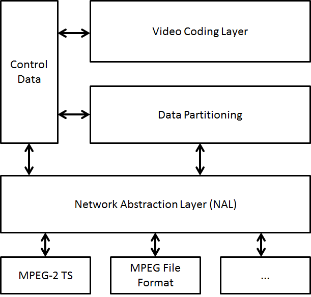
Figure 1 – The AVC layers
AVC is based on the so-called “block based hybrid video coding” approach where a coded video sequence consists of an independently-coded sequence of coded pictures.
- The VCL data for each picture is encoded with a reference to its PPS header data, and the PPS data contains a reference to the SPS header data
- A more sophisticated intra-picture prediction exploiting dependencies between spatially-neighbouring blocks within the same picture, in addition to motion-compensated inter-picture prediction
- Spatial block transform coding exploiting the remaining spatial statistical dependencies within the prediction residual signal for a block region (both for inter- and intra-picture prediction)
- Quarter-sample accuracy and high-quality interpolation filters for motion compensation of the luma component blocks
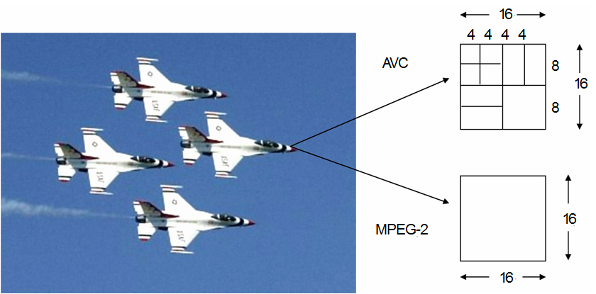
- Transformation (integer approximation of DCT to avoid drift between encoder and decoder picture representations) is defined for block sizes of 4×4 or 8×8
- Basic building blocks of the encoding process are macroblocks of size 16X16 down to to 4X4, e.g., for motion compensation (MC) and linear transformation
- Adaptive de-blocking filter in the prediction loop
- References for prediction of any macroblock from one of up to F previously decoded pictures
- A picture may be split into one or several slices, i.e. sequences of macroblocks which are typically processed in the order of a raster scan
- Slice-wise definition of B-type, P-type, and I-type pictures
- Two different entropy coding mechanism
- Context-Adaptive VLC (CAVLC)
- Context-Adaptive Binary Arithmetic Coding (CABAC)
- The hypothetical reference decoder (HRD) specifies how/when bits are fed to a decoder and how decoded pictures are removed from a decoder
- Supplemental Enhancement Information (SEI) is made available to a decoder in addition to video data
Figure 2 shows the innovation broght about by point 6. of the list above
 |
 |
Figure 2 – Variable macroblock size in AVC
Figure 3 shows the innovation implied by point 8. in the list above
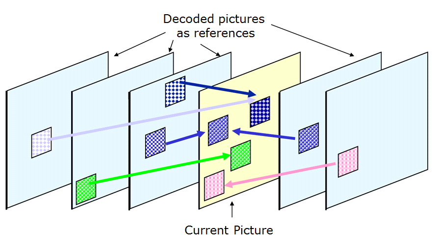
Figure 3 – Multiple reference frames in AVC
Several profiles have been defined, some of which are
- Baseline, Main, and Extended Profiles primarily for applications of “entertainment-quality” video, based on 8-bits/sample, and 4:2:0 chroma sampling
- Full range extensions (FRExt) for applications such as content-contribution, content-distribution, studio editing and post-processing
- Professional quality (PQ) extensions for applications requiring 4:4:4 color sampling and more than 10 bit/sample
The AVC endeavour kept its promise of reducing by half the performance of MPEG-2 Video.
At the same meeting the JVT was established, MPEG started an investigation in video scalability that eventually led to the development of requirements for Scalable Video Coding (SVC). In a nutshell these imply that the encoded video stream should be structured into a base layer stream, decodable by a non-scalable decoder and one or more enhancement layer stream(s) decodable aware of the SVC standard syntax. A Call for Proposals was issued and this work item, too, was entrusted to the JVT’.
The enhancement layer(s) defined by the SVC standard can actually work on top of any base layer video coding standard.
SVC is based on a layered representation with multiple dependencies. Frame hierarchies are needed to achieve temporal scalability so that frames that are not used as references for prediction of layers that are still present can be skipped, as indicated in Figure 4 where pictures marked as “B3” can be removed to reduce the frame rate by a factor of 3, and by removing those marked “B2” the frame rate is reduced by a factor of 2 etc.
 Figure 4 – SVC frame hierarchy
SVC offers a high degree of flexibility in terms of scalability dimensions, e.g. it supports various temporal/spatial resolutions, Signal-to-Noise (SNR)/fidelity levels and global/local Region of Interest (ROI) access). SVC performs significantly better and is much more flexible in terms of number of layers and combination of scalable modes than the scalable version of MPEG-2 Video and MPEG-4 Visual, while the penalty in compression performance, as compared to single-layer coding, is almost negligible.
For the purpose of spatial scalability, the video is first downsampled to the required spatial resolution(s). The ratio between frame heights/widths of the respective resolutions does not need to be dyadic (factor of two). Encoding as well as decoding starts at the lowest resolution, where an AVC compatible “base layer” bitstream is typically used. For the respective next-higher “enhancement layer”, three decoded component types are used for inter-layer prediction from the lower layer:
- Up-sampled intra-coded macroblocks;
- Motion and mode information (aligned/stretched according to image size ratios);
- Up-sampled residual signal in case of inter-coded macroblocks.
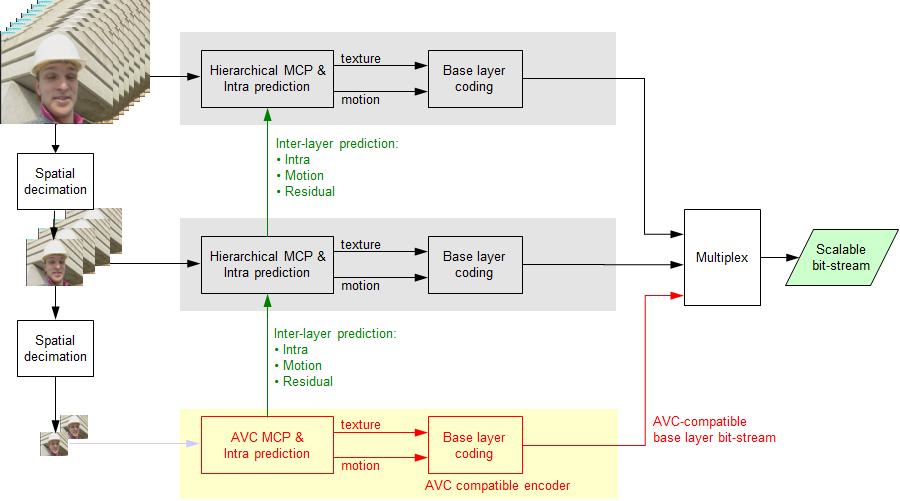
Figure 5 – SVC block diagram
The seminal work on Multiview Video Coding carried out in MPEG-2 Video was extended for MPEG-4 Visual. In AVC Multiview Video Coding further work was done to improve coding of multiview video. The overall structure of MVC defining the interfaces is illustrated in Fig. 6.
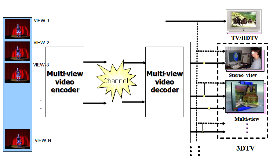
Figure 6 – MVC model
The encoder receives N temporally synchronized video streams and generates one bitstream. The decoder receives the bitstream, decodes and outputs N Video signals that can be used for different purposes: to generate 1 view or N views of a stereo view.
Prediction across views, as shown in Fig. 7, is used to exploit inter-camera redundancy with the limitation that inter-view prediction is only effected from the same time instance and cannot exceed the maximum number of stored reference pictures
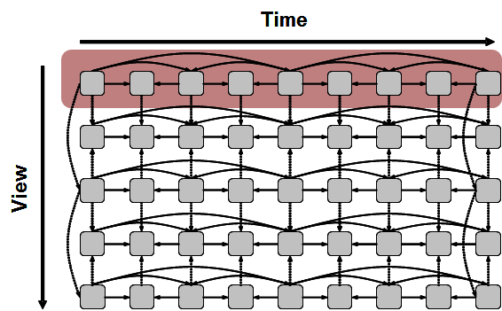
Figure 7 – MVC prediction
The base view is independent of any other view and is AVC compatible that can be extracted to provide a compatible 2D representation of the 3D version.
| Previous chapter | Next section | Next chapter | |
| ToC | Computers And Internet | MPEG-4 – Impact | Software And Communication |