MPEG-1’s formal name is ISO/IEC 11172. ISO/IEC refers to the fact that the standard is recognised by both ISO and IEC because JTC 1, the Technical Committee under which MPEG operates, is a joint ISO and IEC Technical Committee. The number “11172” is a 5-digit serial number that the ISO Central Secretariat assigns to identify a new project of standard and that follows it throughout its life cycle.
The title of MPEG-1 is rather convoluted: “Coding of moving pictures and associated audio for digital storage media at up to about 1,5 Mbit/s”. To make things worse, it is also not very true. MPEG-1 can very well be used in other environments than digital storage media and the reference bitrate of 1.5 Mbit/s (the comma used in the 1,5 of the title is because of ISO conventions) – the original driver of the work – appears only in the title, but is nowhere normatively referenced in the text of the standard. More about this later in this page.
A major departure from other similar standards, such as those produced by the ITU-T in the audio coding domain, is that MPEG-1 does not define an End-to-End “delivery system”, it only defines the receiving end of it. Actually, it does not even do that, because the standard only provides the “information representation” component of the audio-video combination, in other words the format of the information (bitstream) entering the receiver. This feature was common with most MPEG standards.
Philosophically this is quite pleasing and is the implementation of a principle that should drive all communication standards: define how to understand the message, not how to build the message. In other words, a communication standard (I would submit that this should be true for all standards, but this would take me astray) should specify the bare minimum that is needed for interoperability. A standard that over-specifies the domain of its applicability is likely to make more harm than good. On the other hand, what is the purpose of a standard that does not address interoperability? When I hear members of some standards committees stating: “from now on we will work on interoperability”, I always wonder what they have been doing until then.
Having MPEG-1 (and all other standards following it) written in a decoder-centric way has been a personal fulfilment. Indeed, back in 1979 I submitted to a COST 211 meeting a version of the H.120 Recommendation re-written with a decoder-centric viewpoint: describe what you do with the serial bits entering the decoder and how they are converted into pixels, as opposed to the encoder-centric viewpoint of the Recommendation that starts from what you do with video and audio pixels entering the encoder and how they are converted into a bitstream on the output wire. Further, the MPEG-1 standard does not say anything about how the coded information is actually carried by a delivery system. It only specifies some general characteristics of it, the most important of which is to be error-free.
This contrasts with the approach that was followed by other, industry-specific, communication standards like Multiplexed Analogue Components (MAC) developed by the EBU in the 1980s.
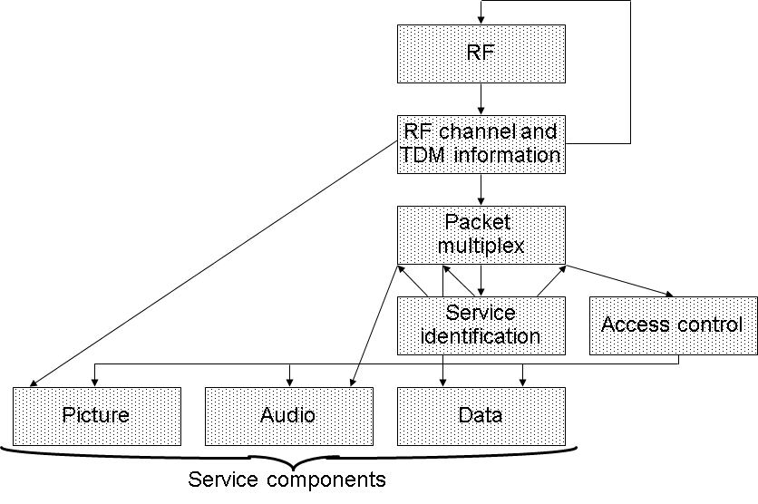
Figure 1 – Multiplexed Analogue Ccomponents (MAC) reference model
Indeed, the MAC standard is a definition of a complete transmission system where everything is defined, from the characteristics of the 11 GHz channel of the satellite link down to the data multiplex, the video signal characteristics, and the the digital audio and character coding. I say “down” because, this is broadcasting, and the physical layer is “up”.
To be fair, I am comparing two systems designed with very different purposes in mind. MAC was a system designed by an industry – European broadcasters – writing a system specification for their members, while MPEG-1 is a specification written for a multiplicity of industries, some of which MPEG did not even anticipate at the time it developed the standard. Even so, I think it is always helpful, whenever possible, to write technical specifications isolating different subsystems and defining interfaces between them.
In this context it is useful to consider the figure below
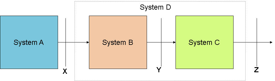
Figure 2 -Standards and interfaces
where System A and System B are separated by Interface X. In MPEG – and in many other standard – interfaces is what a standard is about and nothing else. If an implementation declares that it exposes the X standard interface, then the implemented interface must conform to the referenced standard. The same implementation may claim that it also exposes Interface Y which must conform to the referenced standard or it may be silent on it and then Interface Y in the implementation, may very well not exists or, if it does, it may be anything the manufacturer has decided.
Defining interfaces in a standard makes the design cleaner, it facilitates reusability of components and creates an ecosystem of competing suppliers from system level down to component level. This last point is the reason why the open interface approach to standards is not favoured by some industries – say telco manufacturers – and the reason why IT products have overtaken part of their original business.
MPEG-1 is then another departure from the traditional view of standards as monoliths.
Even though the three parts of ISO/IEC 11172 are bound together (“one and trine”, as MPEG-1 was called), users do not need to use all three of them. Indeed, a “part” of a standard is itself a standard, so it is possible to only use the Systems part and attach proprietary audio and video codecs. Not that this is encouraged, but this “componentisation” approach extends acceptance of the standard and lets more manufacturers compete without preventing the provisioning of complete system. It is clear that, if some customers do not need or want to have the pieces of the standard (providing an interface cost more than having no interface at all), they can order a single system from one supplier without interfaces.
The figure below depicts the components of the MPEG-1 standard.
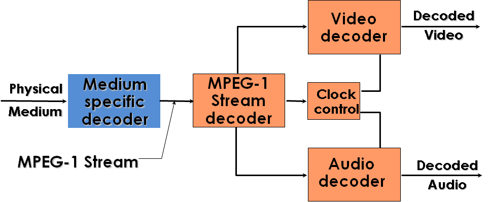
Figure 3 – MPEG-1 Reference model
Systems
Serial bits arrive at the MPEG-1 decoder from a delivery medium-specific decoder (e.g. the pick up head of a CD player) and are interpreted by the Systems decoder that passes on “video bits” to the Video decoder and “audio bits” to the Audio decoder along with other information.
The Systems decoder processes the other non-audio and non-video bits contained in the bitstream, i.e. those carrying timing and synchronisation information, and the result of the processing is handed over to the Video and Audio decoders. It is to be noted that MPEG-1 is capable of handling an arbitrary number of compressed video and audio streams with the constraint that these must all have the same time base.
Two main pieces of timing information are extracted by the system decoder and passed on to the audio and video decoders: the Decoding Time Stamp (DTS) telling a decoder when to decode the video or audio information that has been so time-stamped and the Presentation Time Stamp (PTS) telling a decoder when to present (i.e. display, in the case of video) the video or audio information that has been so stamped. In this way an MPEG-1 stream is a self-contained piece of multimedia information that can be played back without the need of a lower-layer entity, such as a transport.
MPEG-1 Systems specifies how bitstreams of compressed audio and video data are combined. A packet-based multiplexer serialises the audio and video streams and keeps them synchronised. MPEG-1 Systems assumes that the reference time base is provided by a Systems Time Clock (STC) operating at 90 kHz (=1/300 of the 27 MHz sampling frequency used for digital video). STC values are represented with 33-bit accuracy and incremented at 90 kHz rate. The bitstream carries its own timing information in the Systems Clock Reference (SCR) fields. PTSs, represented with 33-bit accuracy, give the time the author expects the audio or video information to be presented. Note that MPEG-1 does not say anything about the use that will be made of audio or video samples, because MPEG-1 is silent on how decoded samples are actually presented. The processing of an MPEG-1 bitstream requires a buffer. Therefore MPEG-1 Systems utilises a Systems Target Decoder (STD) model and DTSs. The latter are required because MPEG-1 Video makes use of B-pictures which imply that pictures at the decoder side are reordered.
Video
The input video can be modeled as three 3D arrays of pixels, where the first two dimensions relate to the spatial visual information and the third one corresponds to time. The MPEG-1 Video coding can be defined as a function producing a bitstream taking three 3D arrays of pixels as input. However, unlike other standards, such as H.261, MPEG-1 does not have any pre-specified value for these 3D arrays of pixels. In particular, it says nothing about the size of the picture, that can be any value up to the maximum size of 4,096×4,096 pixels, and also says nothing about the time spacing between two consecutive 2D arrays of pixels (i.e. frame frequency) that can assume any value from slightly more than 1/24 s to 1/60 s. The only major – and deliberate – constraint is that the spatial position of pixels in consecutive pictures be the same. In other words MPEG-1 Video can only handle “progressive”, i.e. not interlaced, pictures.
Keeping the described flexibility in terms of number of pixels per line, lines per picture and pictures per second is the right thing to do when writing a standard that is conceived as an abstract Signal Processing (SP) function that operates on the three 3D arrays of pixels to produce a bitstream at the decoder and performs the opposite functions at the decoder. Obviously it is not the right thing to do when a company makes a specific product because a decoder capable of decoding any picture size at any bitrate must be so overdesigned that its cost can easily put the product out of the market.
This is the reason why MPEG-1 Video specifies a set of parameters, called Constrained Parameter Set (CPS), given by the table below. This correspond to a “reasonable” set of choices for the market needs at the time the standard was produced.
Table 1 – MPEG-1 Video Constrained Parameter Set
| Parameter | Value | Units |
| Horizontal size | ≤768 | Pixels |
| Vertical size | ≤576 | Lines |
| No. of macroblocks/picture | ≤396 | |
| No. of macroblocks/second | ≤9900 | |
| Picture rate | ≤30 | Hz |
| Interpolated pictures | ≤2 | |
| Bitrate | ≤1,856 | kbit/s |
The maximum number of horizontal pixels – 768 – was a commonly used value for computer displays when MPEG-1 was approved and the maximum number of scanning lines is the number of active lines in a PAL frame. 396 is the maximum number of macroblocks/picture for a “PAL” SIF (288/16 x 352/16), the corresponding value for “NTSC” SIF being 330 (240/16×352/16), and the maximum number of macroblocks/second is the same for both PAL and NTSC (396×25 and 330×30, respectively). The maximum bitrate is the net bitrate in a 2,048 kbit/s primary multiplex when one time slot has been used for, say, audio (29×64) in addition to TS0 and TS16, which are not available for the payload. This is the only place where a number, somehow related to 1.5 Mbit/s of the title, is used.
This table highlights the fact that an implementation of an MPEG-1 Video decoder is constrained by the size of the RAM (a multiple of 288×352), the number of memory accesses per second (a multiple of 288x352x25 or 240x352x30), the bitrate at the input of the decoder and the number of pictures that can be interpolated. Therefore the hardware constraints are independent of whether the pictures are from an NTSC or PAL source.
As mentioned above, MPEG-1 Video is basically an outgrowth of H.261 with some significant technical differences mentioned above and the flexibility of video formats that were limited to CIF or ¼ CIF in H.261. The Figure below represents a general motion compensated prediction and interpolation.

Figure 4 – General scheme of motion compensated prediction and interpolation video coding
The first is the introduction of an “intraframe mode” (called I-pictures) that can be used to insert programmed entry points where information does not depend on the past, as a series of predictive pictures (called P-pictures) would make it. This is one major requirement coming from the flagship application of “storage and retrieval on Digital Storage Media” (but the same requirement exists for “tuning in” a broadcast programme). The second is the the addition of frame interpolation (called B-pictures) to frame prediction.MPEG-1 Video has then 3 types of pictures as depicted in the figure below.

Figure 5 – Picture types in MPEG-1 Video
This feature had been considered in the development of H.261 but discarded because of the coding delay it created for real-time communication. Indeed, for “storage and retrieval on DSM”, the short additional delay caused by B-pictures is largely compensated for by the considerable improvement in picture quality. It is also clear that the more pictures are interpolated, the more memory is needed and for this reason the CPS restricts this flexibility to up to 2 B-pictures.
The figure below represents the hierarchical nature of MPEG-1 Video data whose elements are Group of Pictures (GOP), enclosed between two I-pictures, Pictures, Slices, Macroblocks (made of 4 Blocks) and Blocks (made of 8×8 pixels).

Figure 6 – Hierarchy of MPEG-1 Video
Slices are another departure from the Group of Block (GOB) structure of H.261. Three of the other technical changes are the increase in the motion estimation accuracy to ½ pixel, the removal of the loop filter, and different types of quantisation.
The coding algorithm processes the 3D array of pixels corresponding to luminance. Pixels in one (x,y) plane at time (t) are organised in 8×8 blocks. If the picture is of type “I”, the DCT linear transformation is applied on all blocks and the resulting DCT coefficients are VLC-coded. If the picture is of type “P”, an algorithm tries to make the best match between a given macroblock at time (t+1) with one macroblock in the picture at time (t). For each macroblock, motion vectors are differentially encoded compared to the immediately preceding macroblock. Each block at time (t+1) is subtracted from the corresponding block at time (t) displaced by the amount indicated by the motion vector. The DCT linear transformation is then applied to the difference block. Motion Vectors and DCT coefficients are VLC-coded applying various tricks to reduce the number of bits required to code these data. If the picture is of type B, each block is interpolated using the available anchors. Different picture types, variable length coding and, obviously, the different amount of motion in different parts of a sequence, make the overall data rate variable.
If the channel has a fixed rate, a first-in-first-out (FIFO) buffer may be used to adapt the encoder output to the channel. The encoder will monitor the status of this buffer to control the number of bits generated by the encoder. Changing quantisation parameters is the most direct way of controlling the bitrate. MPEG-1 Video specifies an abstract model of the buffering system, called Video Buffering Verifier (VBV), in order to constrain the maximum variability in the number of bits that are used for a given picture. This ensures that a bitstream can be decoded with a buffer of known size.
Audio
The algorithm adopted for MPEG-1 Audio Layer I and II is a typical subband-coding algorithm, as represented in the figure below.
 |
 |
Figure 7 – Components of the MPEG-1 Audio codec
PCM audio samples are fed into a bank of polyphase filters with 32 subbands. The filter bank decomposes the input signal into subsampled spectral components. In case of a Layer III encoder, a Modified DCT transform is added to increase the frequency resolution, which is 18 times higher than Layer II. Therefore the filtered or “mapped” samples are called subband samples in Layer I and II, and DCT-transformed subband samples in Layer III. A psychoacoustic model is used to estimate the masking threshold, i.e. the noise level that is just below the perception threshold, and this is used to control quantisation and coding block. An smart encoder knows how to allocate the available number of bits/block so that the quantisation noise is kept below the masking threshold. The allocation strategy and the psycho-acoustic model are not specified by the standard and therefore the model provides the means to differentiate between encoders from different manufacturers. MPEG-1 Audio only provides a very basic informative description of one psycho-acoustic model.
The “bitstream formatting” block assembles the actual bitstream from the output data of the other sources, and adds other information (e.g. error correction) if necessary. The resulting data are then packed in a fixed-length packet of data using a bitstream structure that separates the critical parts needing high reliable transmission. There are four different modes possible. The first two are 1) single channel and 2) dual channel in which two independent audio signals are coded within one bitstream. The second two are 3) stereo in which the left and right signals of a stereo pair are coded within one bitstream and 4) Joint Stereo in which the left and right signals of a stereo pair are coded within one bitstream exploiting the stereo irrelevancy and redundancy. Layer III has a number of features that enable better performance compared to the lower two layers: it uses entropy coding to further reduce redundancy and a buffer to smooth out high variations in output bits, and more advanced joint-stereo coding methods.
At the decoder, bitstream data are read from a delivery medium specific decoder. The bitstream data are unpacked to recover the different pieces of information, and the bitstream unpacking block also detects errors if the encoder applied error-checking. The reconstruction block reconstructs the quantised version of the set of mapped samples. The inverse mapping transforms these mapped samples back into PCM samples.
The figure below expands on the structure of the MP3 encoder.
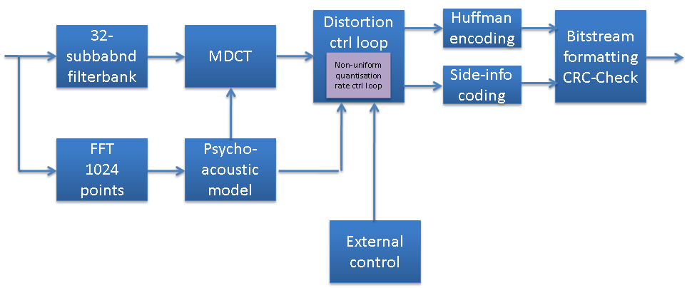
Figure 8 – Mere details of the MP3 encoder
CI would like to conclude this snapshot on MPEG-1 by highlighting the role that my group at CSELT had in developing the first implementation of a full MPEG-1 decoder. Already in 1984 we had started designing a multiprocessor architecture for video coding based on a bus interconnecting a set of multiprocessor boards. The first use of the board was done in 1986 to implement one of the first ISDN videophones. This actually became an industrial product by an Italian company and put in service. Each board featured four Analog Device 2900 Digital Signal Processors (DSP) and one Intel 80186 CPU that controlled communication between the DSPs and between the boards, because each board had in charge only a slice of the picture and data had to be passed to the different boards because of Motion Compensation requirements.
As part of the CSELT work in the COMIS project, my group extended this architecture and implemented the first MPEG-1 Systems, Video and Audio decoding in real time and demonstrated it at the Haifa meeting in March 1992. It should be acknowledged that the MPEG-1 Audio decoding board had been purchased from Telettra.
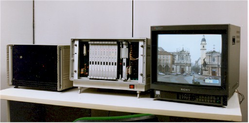
Figure 9 – The COMIS demo
This was not just a technology demonstration because other partners in the COMIS project (BBC, CCETT and Olivetti) had developed content that included multimedia navigation support based on the MHEG standard, then still under development. The screen in the figure above shows an example of that content.
I would like to close this chapter reaffirming that the MPEG-1 standard has been created by the concerted efforts of subgroup chairs during interminable sessions where thousands of technical contributions were debated, some natural leaders who sprang up and took the lead to resolve thorny issues and hundreds of people who took part in all these discussions. I created the environment for this to happen, they have made the standard.